E-Mail:sales@whalescnc.com
E-Mail:sales@whalescnc.com
I. Overview of Numerical Control (NC)
1. Numerical Control (NC)
Numerical control devices decode, process, compute, and control based on input instructions. These are achieved through digital logic circuits and are referred to as hardware numerical control (NC) systems. When most of the work of the numerical control device is completed by a computer system, it is called a Computer Numerical Control (CNC) system. NC is a method of controlling machine tool movement and processing using digital signals. A machine tool equipped with a numerical control system is called a CNC machine tool.
2. Composition of CNC Machine Tools
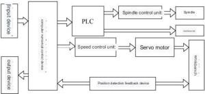
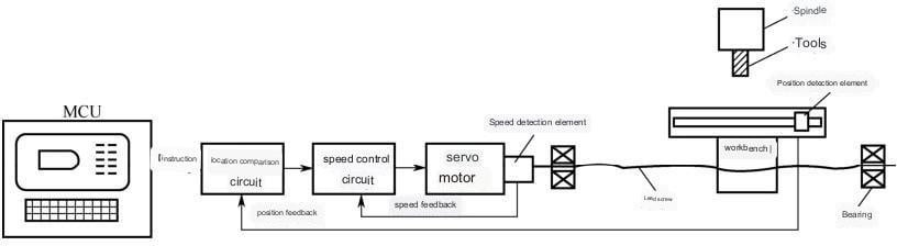
CNC machine tools consist of control media, input/output devices, numerical control devices, servo systems, detection feedback devices, and the machine tool body, as shown in Figure 1-3-1. The numerical control device is the core of the CNC machine tool, and the servo system is the execution part of the CNC machine tool.
- (1) Control Media
The system transfers the processed part processing program information to the numerical control device through related media. This related media is the control medium. Modern CNC machine tools commonly use control media such as transmission software and keyboards. - (2) Input/Output Devices
Input/output devices are interactive devices for information exchange between the machine tool numerical control system and the operator. Input/output devices input information from the control medium to the numerical control device or output information from the numerical control device to the control medium, such as monitors and control panels. - (3) Numerical Control Devices
The numerical control device is the core of the CNC machine tool. It performs digital and logical operations on the input processing program and then sends control signals to the servo system. - (4) Servo System
The main function of the servo system is to receive instruction information from the numerical control device, amplify it after power amplification, and drive the moving parts of the machine tool strictly according to the requirements of the instruction information to process parts that meet the drawing requirements. The servo system consists of driving devices and actuators. Common actuators include stepper motors, DC servo motors, and AC servo motors. - (5) Detection Feedback Devices
The detection feedback device detects the angular displacement of the servo motor or the linear displacement of the CNC machine tool worktable through sensors and converts it into an electrical signal sent to the numerical control system. After comparing it with the command position, the numerical control system sends instructions to the servo system to correct the generated error. - (6) Machine Tool Body
The machine tool body consists of the main drive device, feed drive device, bed and worktable, as well as auxiliary motion devices, hydraulic and pneumatic systems, lubrication systems, cooling devices, etc. Some CNC machine tools are also equipped with special parts such as tool magazines and automatic tool changers. Compared with traditional machine tools, CNC machine tools have undergone significant changes in overall layout, appearance, transmission system, tool system structure, and operating mechanism. They have higher transmission efficiency and a simpler transmission system.
3. Working Principle of CNC Machine Tools
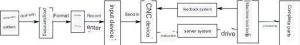
CNC machine tools use digital information to achieve automatic control. The information related to the processed parts is composed of specified text, numbers, and symbols to form a processing program. The processing program is input into the numerical control device through the control medium. After analysis and processing by the numerical control device, various signals and instructions corresponding to the processing program are issued to control the machine tool for automatic processing, as shown in Figure 1-3-2.
II. Classification of CNC Machine Tools
1. Classification by Processing Route Control Features
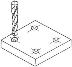
- (1) Point Control
The characteristic of point control CNC machine tools is that the moving parts of the machine tool can only achieve precise positioning from one position to another (Figure 1-3-3). No processing can be performed during the movement and positioning process, and its control system is relatively simple. This type of CNC machine tool mainly includes CNC coordinate boring machines, CNC drilling machines, CNC punching machines, CNC spot welding machines, and CNC pipe bending machines. - (2) Linear Control
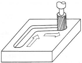
The characteristic of linear control CNC machine tools is that the moving parts of the machine tool can not only achieve precise movement and positioning from one position to another but can also achieve linear cutting motion parallel to the coordinate axis direction (Figure 1-3-4). This type of CNC machine tool mainly includes simple CNC lathes and CNC milling and boring machines.
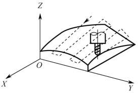
- (3) Contour Control
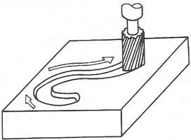
The characteristic of contour control CNC machine tools is that they can control the cutting of two or more coordinate axes simultaneously, thereby controlling the tool to process a certain contour shape, as shown in Figure 1-3-5. Common CNC lathes, CNC milling machines, and CNC grinders are typical contour control CNC machine tools. Their system structure is more complicated than point and linear control systems. During the processing, interpolation calculations must be continuously performed, and then corresponding speed and displacement control is performed.
2. Classification by Servo System Control Features
CNC machine tools can be divided into open-loop control and closed-loop control according to whether there is a detection feedback device for the controlled quantity. In the closed-loop control system, it is further divided into full closed-loop and semi-closed-loop according to the position where the measuring device is placed.
- (1) Open-loop Control
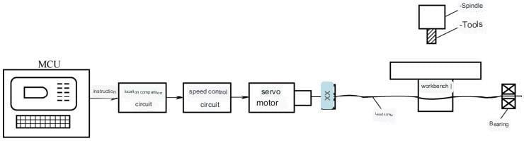
The open-loop control system has a simple structure and low cost, but the system does not detect the actual displacement of the moving parts and cannot correct errors. It is only suitable for medium and small CNC machine tools with not very high machining accuracy requirements, especially simple and economical CNC machine tools (Figure 1-3-6).
- (2) Semi-closed-loop Control
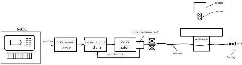
The characteristic of the semi-closed-loop control CNC machine tool is that an angular displacement detection device is installed on the transmission screw of the open-loop control CNC machine tool to indirectly detect the displacement of the moving parts through the screw rotation and then feedback to the numerical control device. The system is easy to debug and has good stability (Figure 1-3-7).
- (3) Full Closed-loop Control
The characteristic of the full closed-loop control CNC machine tool is that a linear displacement detection device is directly installed on the moving parts of the machine tool, and the measured actual displacement value is fed back to the numerical control device, compared with the input command displacement value, and the machine tool is controlled with the difference value to make the moving parts move according to the actual required displacement, ultimately achieving precise movement and positioning of the moving parts, further improving the machining accuracy of the machine tool (Figure 1-3-8).
3. Classification Based on Coordinate Axis Synchronization Features
- (1) Two-Axis Synchronization
This type of CNC machine can simultaneously control the movement of two coordinate axes. For instance, a typical CNC lathe can control the movement of both the X and Z axes, allowing for linear or curved cutting processes. - (2) Two-and-a-Half Axis Synchronization
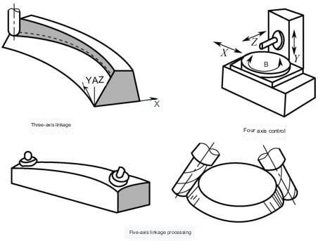
For these CNC machines, while they have three coordinate axes capable of moving in three directions, the control system can only simultaneously control any two of these axes. The third axis can only perform equidistant periodic movements. Early CNC milling machines often used this type of control, though it’s less common now. - (3) Three-Axis Synchronization
These CNC machines have three coordinate axes and can control all three simultaneously. An example would be a CNC milling machine. - (4) Multi-Axis Synchronization
These CNC machines have four or more coordinate axes, and the control system can simultaneously control four or more axes. An example would be a CNC milling machining center.
IV. Classification of CNC Milling Machines
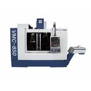
- 1. Vertical CNC Milling Machine
The main spindle axis of the vertical CNC milling machine is perpendicular to the horizontal plane. This type of CNC milling machine is the most widely used. Depending on the size, the movement in the X, Y, and Z directions can be accomplished by the worktable. For larger vertical CNC milling machines, considerations for increased travel, rigidity, and other technical issues often lead to a columnar design where the spindle box and the main spindle (Z-axis) can move up and down along the vertical guide of the column.
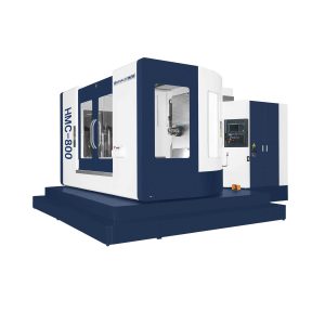
- 2. Horizontal CNC Milling Machine
The main spindle axis of the horizontal CNC milling machine is parallel to the horizontal plane. When using a horizontal CNC milling machine, the tool is mounted on the main spindle, boring bar, or faceplate, and the workpiece is mounted on the worktable, which can move in longitudinal and transverse directions.
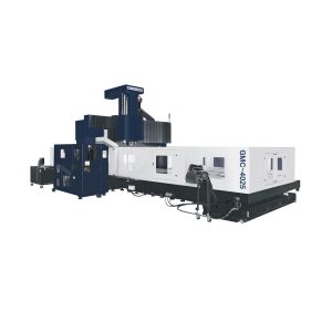
- 3. Double Column Machining Centers
The Double Column Machining Centers has sufficient rigidity, high efficiency, convenient operation, simple structure, and comprehensive performance. It is suitable for milling various large and medium-sized parts made of black or non-ferrous metals.
V. Features of Parts Processed by CNC Milling Machines
- [1] Parts with complex geometric shapes.
- [2] Parts produced in small batches or multiple times.
- [3] Parts that require multiple processing steps during the machining process.
- [4] Parts with a large amount of cutting allowance.
VI. Machining Objects of CNC Milling Machines
CNC milling is one of the most commonly used and primary CNC machining methods. In addition to processing various parts that can be processed by ordinary milling machines, it can also process various parts that ordinary milling machines cannot process. Based on the characteristics of CNC milling machines, the main machining objects suitable for CNC milling are as follows:
- 1. Flat Parts
Parts whose machining surfaces are parallel or perpendicular to the horizontal plane, or parts whose machining surfaces form a certain inclination angle with the reference plane.
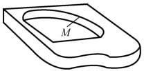
- 2. Curved Parts
Parts with machining surfaces that are spatial curves. These surfaces cannot be unfolded into a plane. During machining, the milling cutter always contacts the machining surface at a point. Ball end mills are commonly used to machine these surfaces.
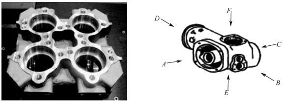
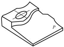
- 3. Box-Type Parts
Box-type parts generally refer to parts with one or more hole systems, with certain internal cavities or cavities, and have a certain proportion in length, width, and height.