E-Mail:sales@whalescnc.com
E-Mail:sales@whalescnc.com
Manual Operation
1.Homing Operation
Steps:
① Rotate the MODE knob to the HOME position. In the HOME mode, press the direction keys for each axis to move them towards the mechanical origin, or press the Z Y X 4 HOME button to return all axes to the mechanical origin in sequence.
Note: Before homing, you should move each axis away from its origin by more than 100mm in either the HANDLE MODE or RAPID mode.
② Press the X+ or X- button, and the X-axis will move towards the mechanical origin. At this time, the X-axis LED will flash. It will stop flashing and remain lit once the X-axis reaches the mechanical origin, indicating the X-axis mechanical coordinate is 0.
③ The operation for the Y, Z, and 4 axes is the same as the X-axis.
④ Press the Z Y X 4 HOME button, and all axes will return to their origins in the order of Z, Y, X, and 4. The indicator lights will flash during this process and will remain lit once each axis is at its mechanical origin.
⑤ During the return to the mechanical origin, each axis will move at a rapid feed rate until it reaches the deceleration point, then move at a speed of 200mm/min to the origin. The feed rate can be adjusted using the rapid feed rate adjustment knob during the rapid movement.
2.Continuous Feed Manual Operation
(1) Slow Feed Operation
The slow feed operation panel is shown in Figure 4.8. The operation is as follows:
Steps:
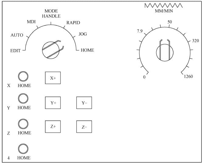
① Rotate the MODE knob to the JOG position. In this mode, pressing the X+ button will move the X-axis in the + direction at the speed selected by the slow feed adjustment knob. The operation for the Y, Z, and 4 axes is the same as the X-axis.
② By adjusting the slow feed rate knob, the feed rate can vary from 0 to 1260mm/min, with a feed error not exceeding ±3%.
(2) Rapid Feed Operation
The rapid feed operation panel is shown in Figure 4.9. The operation is as follows:
Steps:
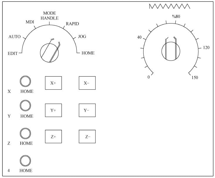
① Rotate the MODE knob to the RAPID position. In this mode, pressing the X+ button will move the X-axis in the + direction at the speed selected by the rapid feed adjustment knob. The operation for the Y, Z, and 4 axes is the same as the X-axis.
② By adjusting the rapid feed rate knob, the rapid feed rate can produce the following variations:
F0 = 0mm/min
100% = X-axis 20000mm/min
Y-axis 20000mm/min
Z-axis 12000mm/min
4-axis ______r/min
3. Handwheel Feed Manual Operation
The handwheel feed manual operation panel is shown in Figure 4.10. The operation is as follows:
Steps:
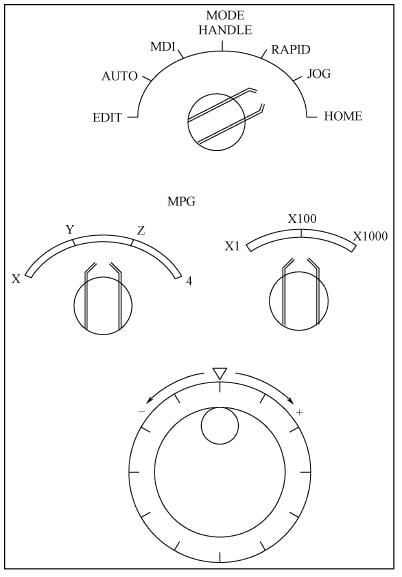
① Rotate the MODE knob to the HANDLE position. In this mode, you can use the handwheel to move each axis. On the handwheel operation panel, select the axis you want to move and the rate for each rotation increment.
② Rotate the axis selection knob to choose the X, Y, Z, or 4 movement axis. When using the handwheel, only single-axis operation is possible.
③ Using the rate selection knob, choose the displacement amount for each rotation of the handwheel. The knob can adjust in three settings: 0.001mm, 0.01mm, and 0.1mm.
④ Rotating the handwheel one full turn (360°) will produce 100 pulses. If the handwheel is rotated clockwise (CW), the movement axis will move in the “+” direction. If rotated counterclockwise (CCW), the movement axis will move in the “-” direction.
4. Spindle Operation Manual Control
In manual operation modes (HANDLE, RAPID, JOG, HOME), the spindle operation can be controlled by the following four buttons, as shown in Figure 4.11.
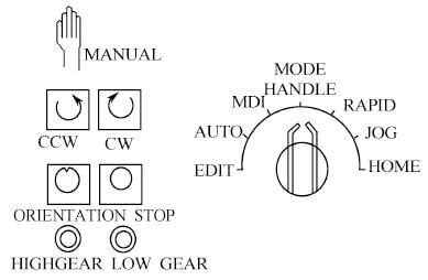
(1) Spindle Clockwise Rotation Button
In manual mode, pressing the CW button will cause the spindle to rotate clockwise at the speed of its last rotation. When rotating clockwise, the light inside the button will illuminate.
(2) Spindle Counterclockwise Rotation Button
In manual mode, pressing the CCW button will cause the spindle to rotate counterclockwise at the speed of its last rotation. When rotating counterclockwise, the light inside the button will illuminate.
(3) Spindle Stop Button
In manual mode, pressing the STOP button will halt the spindle’s rotation. Whenever the spindle is not rotating, the light inside this button will illuminate, indicating that the spindle is in a stopped state.
(4) Spindle Orientation Button
In manual mode, pressing the ORIENTATION button will orient the spindle. Once the spindle is oriented, the light inside the button will illuminate.
If the spindle is rotating and the mode is switched to automatic mode (AUTO/MDI), the spindle will immediately stop.
Ⅱ.MDI Operation
MDI (Manual Data Input) allows for manual input of a command or a segment of program instructions. It can then immediately execute the command as if it were an automatic operation. This function can be used to change the current command mode or to execute a command action. For instance, inputting G55 will change the current coordinate system to G55; inputting M08 will turn on the cutting fluid; inputting S1000 M03 will start the spindle rotating clockwise at 1000r/min; inputting G00 X200 Y100 will quickly position the tool at the specified point.
1. Program Creation
Set the mode selection knob to the MDI position. Pressing the PRGRM button will display the CRT screen as shown in Figure 4.12.
When creating an MDI program, the following points should be noted:
(1) The program number O0000 is automatically inputted.
(2) Program editing is the same as the EDIT mode.
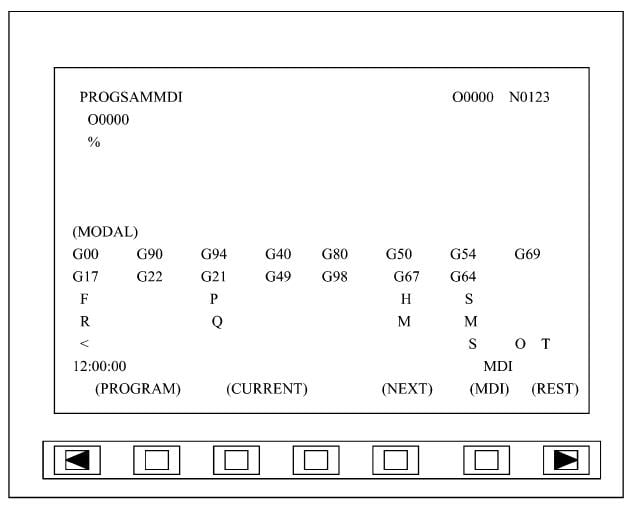
(3) In MDI mode, you can edit up to 6 lines of the program. If it exceeds 6 lines, the % will disappear, and insertion or transformation cannot be performed.
(4) If the last segment of the program is M02 or M30, it will automatically RESET the data in the buffer to avoid affecting subsequent operations and program execution errors.
(5) If you want to delete the entire edited program, press O followed by the DELET or RESET button.
The format and creation method of the MDI program are the same as the EDIT mode.
2. Program Execution
Place the cursor at the beginning of the program (or you can start from the middle), press the START button or the CYCLE START button on the operation panel to start executing the program. When the program ends (M02/M30) or reaches %, the created program will automatically disappear.
3. Tool Number Input/Modification
During the use of the machining center, due to misoperation or other reasons, the tool number in the machine tool magazine does not match the displayed tool number. At this time, the tool number needs to be modified to avoid tool collision accidents.
(1) Input Spindle Tool Number
① In MDI mode, input M95 Tn (Tn=T1~T24) to input the spindle tool number.
② Press the CYCLE START button, and the screen display M95 Tn disappears.
③ Press the T#DISPLAY button to check if the input is correct.
(2) Input Tool Arm Tool Number
① In MDI mode, input M94 Tn (Tn=T1~T24) to input the tool arm tool number.
② Press the CYCLE START button, and the screen display M94 Tn disappears.
③ Press the T#DISPLAY button to check if the input is correct.
(3) Input Tool Magazine Tool Number
① In MDI mode, input M93 Tn (Tn=T1~T24) to input the tool magazine tool number.
② Press the CYCLE START button, and the screen display M93 Tn disappears.
③ Press the T#DISPLAY button to check if the input is correct.
4. Automatic Tool Selection/Change
In MDI mode, automatic tool selection/change can be completed. When NC reads the Tn instruction, it automatically performs tool return, tool selection, and tool fetching actions. When NC reads M06, it automatically performs tool exchange between the tool arm and the spindle. If M06 and T instructions are in the same program segment, the automatic tool selection action is performed first, followed by the tool change action.
(1) Automatic Tool Selection Sequence
The VP1050 type machining center uses a fixed tool number type tool magazine and a shortcut tool selection method.
Before tool selection: The tool arm has an old tool, and a new tool is to be selected from the tool magazine. The tool selection sequence is as follows:
① Determine the tool return position (the tool arm is equipped with old tools)
➣ Shortcut judgment (based on the tool number of the old tool on the tool arm);
➣ Rotation count (tool magazine rotation).
② Return the tool (first return the old tool on the tool arm)
➣ The slide moves above the tool arm (above the tool handle);
➣ The sleeve descends (into the tool handle);
➣ The slide moves into the tool magazine (the tool handle moves from the tool arm to the tool magazine);
➣ The tool number on the tool arm is set to 0 (the tool number on the tool arm is registered as 0);
➣ The sleeve rises (detached from the tool handle).
③ Tool selection
➣ Shortcut judgment (based on the position of the new tool number);
➣ Rotation count (tool magazine rotation).
④ Fetch the tool (then grab the newly selected tool)
➣ The sleeve descends (into the tool handle);
➣ The slide moves to the tool arm (the tool handle moves from the tool magazine to the tool arm);
➣ Update the tool number on the tool arm (the tool on the tool arm is registered as the tool number in the tool magazine);
➣ The sleeve rises (detached from the tool handle);
➣ The slide moves into the tool magazine (initial preparation state).
After tool selection: The tool arm is equipped with the requested new tool, and the old tool on the tool arm is returned to the corresponding tool number position in the tool magazine.
(2) Automatic Tool Change Sequence
Before tool change: The spindle is equipped with a tool (Ts), and the tool claw on the tool library side of the tool arm has prepared a tool (Txx). The tool change is performed in the following order:
① The Z-axis returns to the second reference point, and the spindle is positioned;
② The X-axis moves to the second reference point, and the tool number swap begins;
③ The spindle releases the tool;
④ The tool arm descends;
⑤ The tool arm rotates;
⑥ The tool arm rises, and the tool number swap is completed;
⑦ The spindle grabs the tool;
⑧ The X-axis moves to the HOME point.
After the tool change: The spindle is equipped with a tool (Txx), and the tool claw on the tool library side of the tool arm grabs a tool (Ts).
Ⅲ.Manual Operation of the Tool Magazine
1. Tool Magazine Manual Operation Panel
The tool magazine panel is only effective when operated in the tool magazine manual mode. The tool arm, sleeve, and slide are only allowed to operate in the HANDLE/RAPID/JOG/HOME modes. The tool magazine manual operation panel is shown in Figure 4.13. The functions of each key are as follows:

(1) LOCK MANUAL Key Switch
Sets the tool magazine to manual mode.
(2) MANUAL STEP Tool Magazine Manual Start Button
The start button for various actions when the tool magazine is in manual mode.
(3) FAULT RESET Error Clearing Button
This button has three uses:
① After an anomaly in the tool magazine is resolved, press this button to clear the alarm.
② After opening and then closing the tool magazine door, press this button to clear the alarm.
③ After turning the key switch back to the LOCK position, press this button to restore the tool magazine to automatic mode.
(4) Definitions of the tool magazine single-action selection switch are as follows:
① ARM MAGAZINE: Slide moves into the tool magazine.
② ARM MIDDLE: Slide moves towards the tool arm.
③ ARM RELEASE: Sleeve detaches from the tool handle (high position).
④ ARM HOLD: Sleeve engages the tool handle (low position).
⑤ ARM CW: Tool arm rotates clockwise.
⑥ ARM CCW: Tool arm rotates counterclockwise.
⑦ ARM UP: Tool arm rises.
⑧ ARM DOWN: Tool arm descends.
⑨ MAGAZINE CW: Tool chain rotates clockwise.
⑩ MAGAZINE CCW: Tool chain rotates counterclockwise.
2. Conditions for Establishing Tool Magazine Manual Operation Mode
(1) When the tool magazine is not in automatic tool change or tool selection, turn the tool magazine panel key switch to the MANUAL position. If the tool magazine is in automatic tool change or tool selection, wait until the program ends to establish.
(2) If the tool magazine is performing a tool selection action and the RESET or E—STOP button is pressed, or there’s a power outage, it automatically switches to manual operation mode.
3. Conditions for Canceling Tool Magazine Manual Operation Mode
(1) When the tool magazine panel key switch is turned back to the LOCK position, press the FAULT RESET button, and the FAULT RESET light goes out. If it cannot be canceled, it indicates that the tool change mechanism has not returned to its initial state, i.e., the tool arm should be in the upper position, the sleeve should be in the high position, and the slide should be in the tool magazine position. After restoring to the initial state, press the FAULT RESET button to cancel.
(2) If the manual operation mode is caused by canceling the tool selection midway, press the FAULT RESET button twice. The first time, the tool magazine automatically rotates one position forward, and the FAULT RESET light remains on. The second time cancels the manual operation mode, and the FAULT RESET light goes out.
Ⅳ. Safe Operation
Safe operation includes emergency stops, over-travel, and various alarm handling.
1. Alarms
The CNC system has self-diagnostic capabilities for its software, hardware, and failures. This function is used to monitor whether the entire machining process is normal and to give alarms in a timely manner. Common alarm forms include machine self-locking (drive power cut off), screen errors, alarm lights, and buzzer sounds.
2. Emergency Stop Handling
In the event of an emergency during the machining process, press the EMERGENCY STOP button on the mechanical operation panel, and all moving parts of the machine tool will immediately stop while in motion. When this button is pressed, the machine cannot work normally. The method of release varies depending on the machine, but it is usually released by rotating it.
3. Over-travel Handling
During manual or automatic machining, if the moving parts of the machine tool (such as the tool spindle, worktable) exceed their travel limits (software control limit or mechanical limit), it is considered over-travel. When over-travel occurs, the system gives an alarm, the machine locks, the over-travel alarm light is on, and the over-travel alarm content appears in the alarm line at the top of the screen (e.g., “X direction exceeds travel limit”).
(1) Software Control Limit Over-travel
Steps:
① Rotate the MODE knob to the HANDLE position.
② Use the handwheel to move the over-travel axis in the opposite direction to an appropriate position.
③ Press the RESET button to reset the CNC system.
④ Reset the origin of the over-travel axis and restore the coordinate system.
(2) Mechanical Limit Over-travel
Steps:
① Hold down the CYCLE START button to forcibly start the machine’s hydraulic system.
② Rotate the MODE knob to the HANDLE position.
③ Use the handwheel to move the over-travel axis in the opposite direction to an appropriate position, then release the CYCLE START button.
④ Press the RESET button to reset the CNC system.
⑤ Reset the origin of the over-travel axis and restore the coordinate system.
Ⅴ. Automatic Machining
Automatic machining can be carried out in two modes depending on the size of the machining program. First, when the capacity of the machining program does not exceed the memory capacity of the machining center (50KB), the entire machining program can be input into the memory of the machining center for automatic machining. Second, when the capacity of the machining program exceeds the memory of the machining center, the computer is connected to the machining center for online operation, with the program being input and processed simultaneously.
1. Standalone Automatic Machining
In the automatic program execution mode, the CNC system can execute the program in memory, but only one program can be executed at a time. The automatic execution process is as follows:
➣ Input the program into memory.
➣ Select the program to be executed.
➣ Rotate the mode selection knob to the AUTO position.
➣ Press the CYCLE START button to start automatic program execution, at which point the light inside the button illuminates.
The sequence of automatic program execution is:
➣ Read a single instruction from the specified program.
➣ Decode the instruction.
➣ Start executing the instruction.
➣ Read the next instruction.
➣ Decode and store in advance for the next execution.
➣ After the previous instruction, the next instruction can be executed immediately.
➣ Subsequently, repeat reading the next instruction for automatic program execution.
2. Online Automatic Machining
Steps:
① Choose a computer and install dedicated program transfer software (e.g., PCIN software). Set the transfer parameters according to the specific requirements of the machining center.
② Connect the computer and the machining center via the RS—232C serial port.
③ Set the machining center to DNC operation mode.
④ Rotate the mode selection knob to the AUTO position.
⑤ Select the program to be transferred for machining on the computer and press the transfer command.
⑥ Press the start button on the machining center, and online automatic machining begins.
3. Byte Skipping
(1) ON
Press the SLOCK SKIP button, and the light inside the button illuminates. In the AUTO or MDI mode, if there is a / symbol at the beginning of the instruction, this instruction will be skipped and not executed.
(2) OFF
The SLOCK SKIP button is not pressed, and the light inside the button goes out. In the AUTO or MDI mode, even if there is a / symbol at the beginning of the instruction, this instruction will still be executed as usual.
Ⅵ. Program Management Operations
-
Program Input
This function includes the creation of program names and the input of the program.
Steps:
① Turn on the data protection switch.
② Rotate the mode selection knob to the EDIT position.
③ Press the PRGRM button.
④ Enter the program name address O.
⑤ Enter the program number.
⑥ Press the INSRT button to confirm. The above steps complete the establishment of a new program name.
⑦ Enter the content of each program segment and press the INSRT button to confirm (this step completes the input of program content).
-
Program Editing
Program editing includes searching for the program, modifying the program content, deleting, and inserting, etc.
(1) Program Search
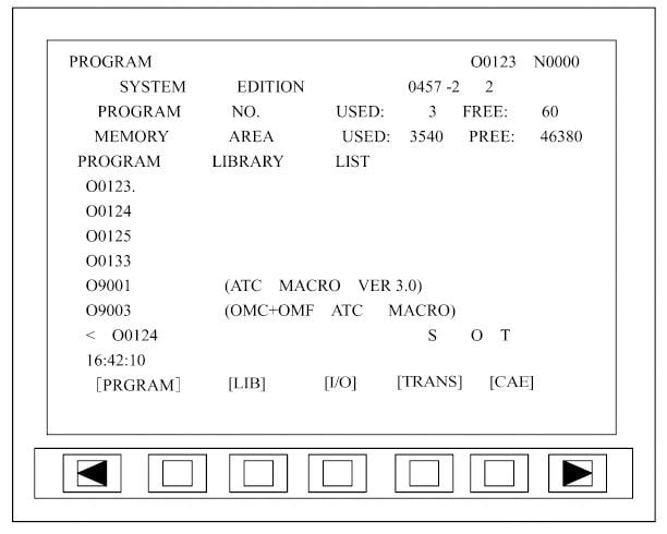
Program search refers to searching for the program name, program segment number, a single instruction in the program, and a word in the program. Figure 4.14 shows the search for the program name O0124.
Steps:
① Turn on the data protection switch.
② Rotate the mode selection knob to the EDIT position.
③ Press the PRGRM button.
④ Enter the program name address O.
⑤ Enter the desired program number 0124 and press the confirm button.
⑥ After the search is completed, the CRT screen displays the found program.
(2) Program Content Search
There are several methods for searching program content, including single instruction search, page search, and specified instruction search.
➣ Single Instruction Search: Press the CURSOR ‘↑’ or ‘↓’ button, and the cursor will search forward or backward from the current position one instruction at a time. Release the CURSOR button when the desired instruction is found.
➣ Page Search: Press the PAGE ‘↑’ or ‘↓’ button to display the program content of the previous or next page. When the desired program segment is found on a page, use the single instruction search method to find the instruction to be modified.
➣ Specified Instruction Search: Enter the instruction to be searched for and press the CURSOR ‘↑’ or ‘↓’ button. The search will start from the current position and move forward or backward. If the desired instruction is found, the cursor will stop at that instruction. If the instruction is not found, the CRT will display a warning message and sound an alarm.
(3) Program Content Modification
Program content modification includes inserting, replacing, and deleting instructions.
➣ Inserting Instructions: In ‘EDIT’ or ‘MDI’ mode, use the search method to move the cursor to the position before where the insertion is needed. Enter the content to be inserted, press the ‘INSRT’ button, and the insertion is complete.
➣ Replacing Instructions: In ‘EDIT’ or ‘MDI’ mode, use the search method to move the cursor to the instruction to be replaced. Enter the replacement content and press the ‘ALTER’ button to complete the replacement.
➣ Deleting Instructions: In ‘EDIT’ or ‘MDI’ mode, use the search method to move the cursor to the instruction to be deleted. Press the ‘DELET’ button to complete the deletion.
(4) Automatic Insertion of Sequence Numbers
Steps:
① Set the SEQ parameter to 1.
② Select ‘EDIT’ mode.
③ Press the ‘PRGRM’ button.
④ Enter the address N.
⑤ Enter the starting value of N, for example, 10.
⑥ Press the ‘INSRT’ button.
⑦ Insert each single instruction data.
⑧ Enter EOB.
⑨ Press the ‘INSRT’ button. The EOB is stored in memory. With the increment value parameter set to 2, N12 is inserted and displayed on the next line.
-
Program Deletion
Steps:
① Rotate the mode selection knob to the ‘EDIT’ position.
② Press the ‘PRGRM’ button.
③ Enter the program name address O.
④ Enter the program number to be deleted.
⑤ Press the ‘DELET’ button to delete the program.
-
Program Verification
After the machining program is compiled, it cannot be used for workpiece machining immediately. It is necessary to verify the correctness of the machining program and the adaptability between the machining program, the machine tool, and the workpiece. Especially for manual programming, program verification is particularly important.
(1) Verification of Program List
Before running the program, the program list should be verified first. If there is an error in the program list, machining errors will inevitably occur, causing waste.
Steps:
① Check if there are any errors or omissions in the function instruction codes. First, check the auxiliary function instruction codes (M) as they are used less frequently in the program. Then check the preparatory function instruction codes (G) against the programming sketch or part drawing. Verify if interpolation instructions G01, G02, G03 are used correctly or omitted, if plane selection G17, G18, G19 is reasonable, if tool offset G41, G42, G40 is used correctly, and if G90, G91 are used in coordination, etc.
② Check the tool code. Verify if the tool code is filled in correctly or omitted to prevent errors in tool radius compensation or tool length compensation.
③ Verify if the data is correct and filled in without errors. Check each node’s data against the programming sketch or part drawing. For program lists written using the relative increment method, verify the correctness of program data based on the characteristic that the tool starts from the tool setting point, finishes machining, and returns to the tool setting point, forming a closed loop. The algebraic sum of the displacement of each coordinate should be zero.
(2) Machining Center Verification
The operation keys for the machining center program verification are shown in Figure 4.15. There are several verification methods.
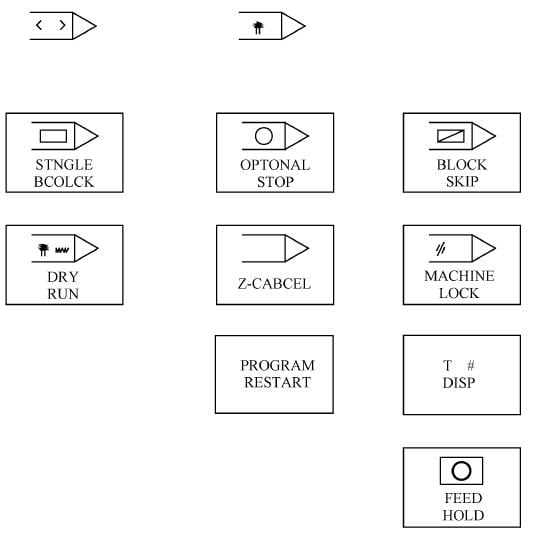
➣ Full-Axis Mechanical Lock: By pressing the “MACHINE LOCK” button, the light inside the button illuminates, indicating that the switch is in the “ON” state, which means all axes are mechanically locked. In this state, even if the CNC system executes NC instructions or manual commands, the mechanical axes of the machine tool do not move. The mechanical coordinate values on the display remain unchanged, but the incremental and absolute coordinate values continue to change. Instructions for M, S, T codes are executed as usual.
➣ Z-Axis Mechanical Lock: When the “Z-CANCEL” button is pressed, the light inside the button illuminates, indicating that the Z-axis mechanical lock switch is in the “ON” state. In manual or automatic operation, the Z-axis does not move. If the button is not pressed, the light inside the button goes out, and the Z-axis mechanical lock switch is in the “OFF” state, meaning the Z-axis feeds normally.
➣ Auxiliary Function Lock: When the “MST LOCK” software key is used to set the auxiliary function lock switch to the “ON” state, the M, S, T, and B commands on the machine tool operation panel are locked. Except for M00, M01, M02, M30, M98, and M99, which will be executed, all other M, S, T instructions will not be executed. When the auxiliary function lock switch is in the “OFF” state, all M, S, T instructions can be executed normally.
(3) Workpiece Trial Cutting Inspection
The material used for trial cutting can be easily machinable plastics or paraffin. However, these often do not reflect the technological issues of the machining program, such as whether the cutting amount is appropriate, whether the surface roughness of the machined part meets the standards, etc. Moreover, it’s not very suitable for large or complex workpieces. Therefore, sometimes it’s bold but practical to trial cut the official blank. To avoid wasting too much material, trial cutting is generally performed after verifying the program list or machine tool. Depending on the specific situation of the workpiece, sometimes layer-by-layer trial cutting can be adopted. This involves raising the tool and enlarging the tool radius compensation value. This approach ensures that one blank can undergo trial cutting several times, yielding more accurate results.


