E-Mail:sales@whalescnc.com
E-Mail:sales@whalescnc.com
Establishment of workpiece CNC coordinate system
1. Coordinate System of the CNC Machining Center
When machining parts on a CNC Machining Center, the relative movement between the tool and the workpiece must occur within a defined coordinate system to ensure normal processing according to the program. The coordinate system interface generally displays the following coordinate systems: relative coordinate system, remaining coordinate system, absolute coordinate system (i.e., the workpiece coordinate system), and the machine coordinate system. In practice, the machine coordinate system and the workpiece coordinate system are crucial. The machine coordinate system is not used for programming but is often used to determine the workpiece coordinate system. It serves as the reference coordinate system for establishing the workpiece coordinate system.
2. Establishment of the Workpiece Coordinate System
(1) Establishing the Workpiece Coordinate System with G92 Command
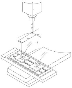
The distance between the origin of the workpiece coordinate system and the origin of the machine coordinate system can be set with the G92 command. For example, assuming the machine origin point as shown in Figure 4.16, the command to establish the workpiece coordinate system with G92 would be:
N1 G92 X100.0 Y-200.0 Z-250.0; (Establishes the workpiece coordinate system with O′ as the origin, completing the position change from the machine reference point to the O′ point in memory. However, the coordinates do not move; the movement of the coordinate axis occurs in the next program segment.)
N2 G00 G90 X-50.0 Y-50.0 Z0; (The tool rapidly moves to the coordinate position within the workpiece coordinate system.)
(2) Setting the Workpiece Coordinate System with G54 to G59
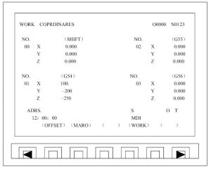
Setting the workpiece coordinate system with G54 to G59 differs from setting it with G92. G92 sets the offset of the workpiece coordinate system relative to the machine coordinate system within the program. G54 to G59 set the offset of the workpiece coordinate system through the offset screen by parameters, as shown in Figure 4.17. The first workpiece coordinate system is set with G54.
Steps
- Accessing the Workpiece Coordinate System Offset ScreenOn the CNC control panel of the machine, press the ‘OFFSET’ key three times to display the workpiece coordinate system offset screen.
- Selecting G54Move the cursor to G54.
- Setting Coordinates
- Press the address key X, then the number key 100.0, followed by the INPUT key.
- Press the address key Y, then the number key -200.0, followed by the INPUT key.
- Press the address key Z, then the number key -250.0, followed by the INPUT key.
After these steps, the G54 workpiece coordinate system is set. The screen will display the results as shown in Figure 4.17. Similarly, the second workpiece coordinate system in Figure 4.16 can be set using any one of G55 to G59. The offset amount can be entered in the same way.
(3) Establishing a New Workpiece Coordinate System Using the Original Workpiece Coordinate System Offset
In actual machining, sometimes a new workpiece coordinate system needs to be established that has a relative relationship with the previously established workpiece coordinate system, such as having an offset in the X, Y, and Z directions. In this case, the method of offsetting the original coordinate system as a whole can be adopted. For example, to establish a new workpiece coordinate system with an overall offset of X20, Y20, and Z10 relative to the original G54-G59 coordinate system, the setting method is as follows:
On the CNC control panel of the machine, press the ‘OFFSET’ key three times to display the workpiece coordinate system offset screen. Move the cursor to the coordinate offset (SHIFT) position. Press the address key X, number key 20, and INPUT key; press the address key Y, number key 20, and INPUT key; press the address key Z, number key 10, and INPUT key. At this point, the origin of the established G54-G59 workpiece coordinate system is no longer the coordinate origin value displayed in the workpiece offset screen for the G54-G59 coordinate system but is added to the corresponding value of the relative coordinate system.
3. Measurement of the Workpiece Coordinate System
After the workpiece is aligned and clamped on the fixture, the coordinate values of the workpiece coordinate system must be correctly measured and input into the offset page. Measuring the coordinate values of the workpiece coordinate system means measuring the programming origin (i.e., the origin of the workpiece coordinate system) in the machine coordinate system.
The method to determine the coordinate values of the workpiece coordinate system is: at a determined position, make the selected programming zero point coincide with the machine spindle axis in the X and Y directions, and coincide with the machine spindle end face (or tool end face) in the Z direction. At this time, the coordinate value under the machine coordinate system is the coordinate value of the established workpiece coordinate system origin.
(1) Measurement of X and Y Coordinate Values
First, use a dial indicator (or micrometer) to align the fixture’s position on the machine table. Then, install a photoelectric measuring head on the spindle, move the machine’s X and Y axes separately, bring the fixture positioning surface close to the measuring head, and measure the distance between the measuring head and the positioning surface to determine the X and Y coordinate values of the programming zero point in the machine coordinate system.
(2) Measurement of Z Coordinate Value
Install a standard measuring rod (or machining tool) on the spindle, move the Z axis, bring the fixture positioning surface close to the measuring rod, and then use a micrometer block to accurately measure the distance H between the measuring rod and the positioning surface. The workpiece coordinate system is: ZW=-|ZM+T+H|, where ZM is the distance the spindle Z axis moves in the machine coordinate system, T is the length of the measuring rod, H is the block size, and ZW is the coordinate value of the spindle end face in the machine coordinate system.
Workpiece Clamping and Alignment
The clamping and alignment of the workpiece are key steps in CNC machining, which require significant attention from the machine operator. Before clamping the workpiece, it’s essential to determine the method of clamping, select the designed workpiece positioning base and fixtures, and then complete the clamping and alignment process.
During the workpiece clamping and alignment, the following points should be noted:
- Workpiece Contour: The external contour of the workpiece should not interfere with the normal movement of the machine, and all machining parts of the workpiece must fall within the working stroke of the machine.
- Installation Direction: The installation direction of the workpiece should be the same as the coordinate direction during programming to prevent any change in machining coordinates.
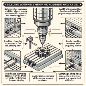
- Tool Setting Point: Try to avoid having clamping aids at the tool setting point on the workpiece to minimize the impact of workpiece installation on tool setting.
- Alignment Edge: The long edge used for alignment on the workpiece should be consistent with the longitudinal direction of the machine table, facilitating the alignment of the workpiece.
- Clamping Screw Position: The position of the clamping screws should not affect the entry and exit of the tool; the height of the clamping screws should be as low as possible to prevent collisions with the tool when it rapidly reaches the machining safety height from any position.


