E-Mail:sales@whalescnc.com
E-Mail:sales@whalescnc.com
Plane Milling
Plane surfaces on a workpiece can be categorized into non-machined and machined surfaces. Machined surfaces are those that require specific accuracy and surface roughness, and are obtained through mechanical machining. Plane components are the most common and relatively simple objects in CNC milling. They can generally be processed using two-axis linkage on a three-axis CNC milling machine.
1 Common Clamping Devices and Methods
When machining planes on CNC milling machines and machining centers, precision vices and clamping bolts are commonly used to secure the workpiece. For some complex workpieces that cannot be clamped using precision vices and clamping bolts, combination fixtures and special fixtures can be used.
(1) Precision Vices
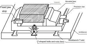
As shown in Image 3-1, a precision vice mainly consists of a fixed jaw and a movable jaw. The setup process of a precision machine vice on a CNC machine is as follows:
The base of the precision machine vice has embedded positioning keys. During installation, place these keys into the T-slots on the worktable to obtain the correct position on the milling machine. Alternatively, manually align it (for horizontal machining centers, use a 90° angle plate and position the movable jaw of the vice on top). Tighten the vice using T-bolts and nuts. Adjust the positioning and clamping blocks, and then place and clamp the workpiece between the two jaws of the vice.
Precision vices are the main accessories for CNC milling machines and are suitable for clamping workpieces that are simple in shape, regular, and small in size.
(2) Clamping Bolts
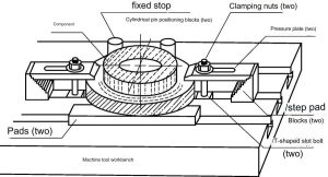
For large workpieces or those that are difficult to clamp using precision vices, clamping bolts can be used to directly secure the workpiece to the worktable for machining, as shown in Image 3-2. The setup process for the clamping bolts is as follows:
Fix the positioning pins into the T-slots of the machine table and place the base plate on the worktable. Choose appropriate clamping plates, step blocks, and T-bolts, and place them in their corresponding positions. Clamp the workpiece (if the clamping surface is a precision-machined surface, use a shim to protect it).
2 Plane and Step Surface Milling
(1) Milling Cutters
Milling cutters are multi-toothed tools. During milling, multiple teeth are engaged in the work simultaneously, resulting in high productivity. In each revolution, each tooth only engages in cutting once, spending most of its time in a dormant state, which allows for better heat dissipation. During milling, the cutting thickness of each tooth varies, causing impact as the teeth enter or exit the material. Therefore, the milling process is not smooth and is prone to vibrations.
(2) Selection of Main Parameters for Milling Cutters
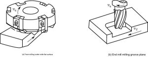
When milling planes on CNC milling machines, the most commonly used cutters are indexable face mills and end mills (as shown in Image 3-3). Sometimes slot milling cutters are used, but they have fewer teeth and cause more vibration during plane milling, resulting in lower feed rates and are generally less commonly used. Therefore, the focus here is on the selection of parameters for face mills and end mills.
① Selection of Main Parameters for Face Mills
a. Material of the tool: The material of the tool is a key characteristic, regardless of whether the tool has a coating or how much it costs. For milling operations, it plays a crucial role.
b. Diameter of the milling cutter: The standard diameter for indexable face mills ranges from ϕ16 to 630mm. The appropriate diameter should be chosen based on the radial depth of cut (ae) to cover the entire width of the workpiece, thereby improving machining accuracy and efficiency, reducing tool marks, and ensuring tool durability.
c. Number of teeth: Indexable face mills come in coarse, fine, and extra-fine teeth. Coarse-toothed mills have larger chip pockets and are commonly used for rough milling steel parts and castings with interrupted surfaces. Fine-toothed mills are used for milling steel parts under stable conditions. Extra-fine toothed mills have smaller chip loads per tooth and are mainly used for machining thin-walled castings.
d. Geometric angles of face mills: The selection principle for the rake angle is similar to that of turning tools. However, due to the impact during milling, the rake angle is generally smaller than that of turning tools, especially for carbide face mills.
② Selection of Main Parameters for End Mills
a. Material of the tool: Similar to face mills, the material of the tool is a key characteristic, regardless of whether the tool has a coating or how much it costs.
b. Rake and clearance angles: Both the rake and clearance angles for end mills are positive and are selected based on the material of the workpiece and the diameter of the milling cutter.
c. Overall length of the tool: If the operation allows, shorter end mills should be used to minimize deviations during milling. Therefore, short end mills are preferred to save on tool costs.
d. Number of flutes: The increase in the number of flutes makes chip evacuation more difficult but improves the surface quality of the machined part. Two-flute and four-flute tools are common. The appropriate number of flutes should be chosen based on the material being machined.
Two flutes: Have the largest chip pockets and are commonly used for general milling operations and for milling softer materials.
Three flutes: Very suitable for drilling operations and also for general milling. Chip evacuation and machining quality are intermediate.
Four flutes: Suitable for harder ferrous metal operations with higher machining quality.
Six and eight flutes: Tools with a large number of flutes have reduced chip evacuation capabilities but improved surface quality, making them particularly suitable for final product machining.
(3) Up-milling and Down-milling
Up-milling and down-milling are shown in Image 3-4.
① Characteristics of Up-milling
a. Cutting thickness decreases from large to small.
b. The path traveled by the teeth on the workpiece is short.
c. Ordinary milling machine tables may have backlash (CNC machines use ball screws, effectively solving the problem of backlash in the screw-nut pair, so there is no table backlash issue).
d. Not suitable for machining workpieces with a hard skin.
e. Larger average cutting thickness, smaller cutting deformation.
f. Lower power consumption (when milling carbon steel, power consumption can be reduced by 5%, and when milling difficult-to-machine materials, it can be reduced by 14%).
② Characteristics of Down-milling
a. Cutting thickness increases from small to large.
b. The path traveled by the teeth on the workpiece is long.
c. The tool is prone to wear, and the cold hardening phenomenon on the machined surface is more severe.
Due to the friction and compression of the down-milling tool on the already machined surface, it is easy to damage the surface roughness of the workpiece, and the surface cold hardening phenomenon is more severe, resulting in stress. The surface quality of down-milling is worse than that of up-milling.
3 Methods of Feed in Plane Milling
There are five methods of feed in plane milling: single-pass milling, bidirectional multiple-pass cutting, unidirectional up-milling, unidirectional down-milling, and conventional milling.
For large planes, if the diameter of the milling cutter is greater than the width of the workpiece, the milling cutter can remove the entire large plane in one pass. Therefore, multiple passes at the same depth are not required, and single-pass milling is generally used.
If the diameter of the milling cutter is relatively small and cannot remove the entire large plane in one pass, multiple passes at the same depth are required. Common methods include bidirectional multiple-pass cutting, unidirectional up-milling, unidirectional down-milling, and conventional milling. Each method has different machining conditions under specific environments.
(1) Parameters for Large Plane Milling
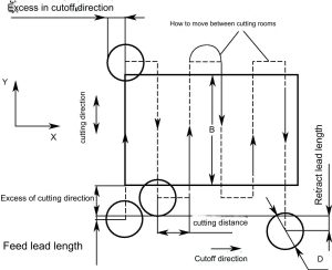
The most typical large plane milling is bidirectional multiple-pass cutting as shown in Image 3-5. There are eight milling parameters: cutting direction, truncation direction, cutting spacing, method of movement between cuts, overcut in the truncation direction, overcut in the cutting direction, lead-in and lead-out lengths. These eight parameters include all the parameters for other large plane milling methods. For ease of programming, the overcut on both sides of the workpiece in the truncation direction is usually the same, and the cutting spacing is evenly distributed.

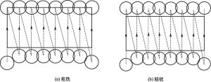
(2) Single-Pass Milling
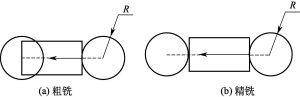
Single-pass milling is actually symmetrical plane milling. The main parameters for single-pass milling include: cutting direction, truncation direction, overcut in the cutting direction, lead-in and lead-out lengths. Single-pass milling is divided into rough milling and finish milling. The cutting parameters for rough and finish milling are different, and the toolpaths are also different, as shown in Image 3-6(a). For rough milling, the milling cutter does not need to completely mill out the workpiece, as shown in Image 3-6(b) for finish milling, the milling cutter needs to completely mill out the workpiece.
The main parameter requirements for rough milling are as follows:
Lead-in length + overcut in the cutting direction > R, generally take R + (3~5), lead-out length + overcut in the cutting direction ≥ 0, generally take 0.
The main parameter requirements for finish milling are as follows:
Lead-in length + overcut in the cutting direction > R, lead-out length + overcut in the cutting direction > R, generally take R + (3~5).
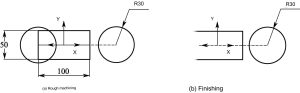
Example: As shown in Image 3-7, milling a 100×50 plane using single-pass milling. The depth for rough milling is 3, and for finish milling, it is 2.
G Code
O0001
N100 G21 ; Set to metric units
N102 G0 G17 G40 G49 G80 G90 ; Initialize system, set working environment
N106 G0 G90 G54 X83. Y0. S350 M3 ; Rough milling: Lead-in + overcut = 33
N108 G43 H01 Z50. ; Safe height + tool length offset
N110 Z3. ; Z-axis reference height
N112 G1 Z-3. F200. ; Move to Z-3 at feed rate of 200
N114 X-50. F80 ; Rough milling, lead-out = 0, complete
N118 G0 Z50. ; Move to safe height
N120 X83. ; Finish milling: Lead-in + overcut = 33
N122 Z3. ; Move to Z3
N124 G1 Z-5. F200. ; Move to Z-5 at feed rate of 200
N126 X-83. F80 ; Finish milling, lead-out + overcut = 33
N130 G0 Z50. ; Move to safe height
N132 M5 ; Spindle stop
N134 G49 ; Cancel tool length offset
N136 G91 G28 Z0. ; Return to machine home position
N138 M30 ; End of program
Note: The lead-out lengths and overcuts in the cutting direction for rough and finish milling are different. This is mainly determined by the characteristics of rough and finish machining. Rough machining mainly focuses on machining efficiency and prepares for finish machining; finish machining mainly ensures the machining quality of the workpiece.
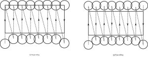
(3) Bidirectional Multiple-Pass Cutting
Also known as Z or bow-shaped cutting, this method is frequently used. The cutting sequence alternates between up-milling and down-milling, as shown in Image 3-8. It is generally not recommended for plane milling. Image 3-8(a) shows rough milling where the milling cutter does not need to completely mill out the workpiece, while Image 3-8(b) shows finish milling where the milling cutter needs to completely mill out the workpiece.
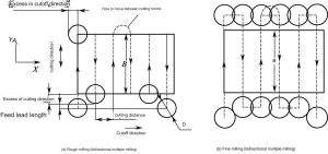
The cutting direction can be along the X-axis or Y-axis, and their principles are exactly the same.
In addition to the main parameters that are the same as those for single-pass milling, bidirectional multiple-pass cutting also includes the following main parameters: cutting spacing, method of movement between cuts, and overcut in the truncation direction. During rough and finish milling, the cutting spacing is less than D (tool diameter). For ease of programming, the method of movement between cuts is generally linear, and the overcut in the truncation direction is generally taken as 50% of D.
Example: As shown in Image 3-9, milling a 100×50 plane with an end mill of diameter ϕ20 using bidirectional multiple-pass cutting. The depth for rough milling is 3, and for finish milling, it is 2.
O0001
N102 G0 G17 G40 G49 G80 G90
N106 G0 G90 G54 X-50.0 Y-38. S800 M3 ; Rough milling: Lead-in length + overcut in cutting direction = 13
N108 G43 H1 Z50.
N110 Z3.
N112 G1 Z-3. F200.
N114 Y25. F80.
N116 X-35.713 ; Cutting spacing = 100/7 = 14.287
N118 Y-25.
N120 X-21.426
N122 Y25.
N124 X-7.139
N126 Y-25.
N128 X7.139
N130 Y25.
N132 X21.426
N134 Y-25.
N136 X35.713
N138 Y25.
N140 X50.0
N142 Y-38. ; Rough milling complete
N144 G0 Z50.
N148 X-50. Y-38. ; Start finish milling
N150 Z3.
N152 G1 Z-5. F200.
N154 Y28. F100 ; Overcut in cutting direction = 3
N156 X-35.713 ; Cutting spacing = 100/7 = 14.287
N158 Y-28.
N160 X-21.426
N162 Y28.
N164 X-7.139
N166 Y-28.
N168 X7.139
N170 Y28.
N172 X21.426
N174 Y-28.
N176 X35.713
N178 Y28.
N180 X50.
N182 Y-38.
N186 G0 Z50. ; Finish milling complete
N188 M5
N190 G91 G28 Z0.
N194 M30
Tip: The cutting interval can generally be calculated by total length/number of intervals.
(4) Unidirectional Up-Milling and Down-Milling
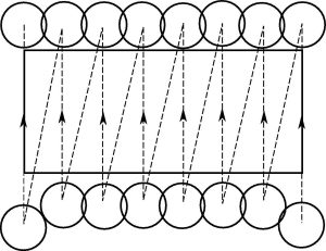
In unidirectional up-milling and down-milling, the entry point of the cutter is at the same position on one axis. After cutting to the specified length, the tool is lifted and moved above the workpiece to change the position on the other axis. This is the most common method for plane milling. Unidirectional milling is divided into up-milling and down-milling. Figure 3-10 shows unidirectional up-milling; for down-milling, you only need to move the entry point to the other side of the workpiece. Unidirectional milling requires frequent rapid return movements, resulting in low efficiency.
The parameters considered in unidirectional up-milling are basically the same as those in bidirectional multiple cutting. You only need to consider the overcut in the cutting direction during rough and fine milling.
Example: As shown in Figure 3-11, milling a 100×50 plane with a vertical milling cutter with a diameter of ϕ20, using unidirectional down-milling. The milling depth is 3.
O0001
N102 G0 G17 G40 G49 G80 G90
N106 G0 G90 G54 X50. Y-50. S800 M3 ; Move to starting position
N108 G43 H1 Z50.
N110 Z3.
N112 G1 Z-3. F200.
N114 Y38. F80.
N116 G0 Z50.
N118 X35.713 Y-38. ; Complete the first reverse milling from N106 to N118
N120 Z3.
N122 G1 Z-3. F200.
N124 Y38. F80.
N126 G0 Z50.
N128 X21.426 Y-38. ; Complete the second reverse milling from N118 to N128
N130 Z3.
N132 G1 Z-3. F200.
N134 Y38. F80.
N136 G0 Z50.
N138 X7.139 Y-38.
N140 Z3.
N142 G1 Z-3. F200.
N144 Y38. F80.
N146 G0 Z50.
N148 X-7.139 Y-38.
N150 Z3.
N152 G1 Z-3. F200.
N154 Y38. F80.
N156 G0 Z50.
N158 X-21.426 Y-38.
N160 Z3.
N162 G1 Z-3. F200.
N164 Y38. F80.
N166 G0 Z50.
N168 X-35.713 Y-38.
N170 Z3.
N172 G1 Z-3. F200.
N174 Y38. F80.
N176 G0 Z50.
N178 X-50.0 Y-50.
N182 G1 Z-3. F200.
N184 Z3.
N184 Y38. F80.
N186 G0 Z50.
N188 M5
N190 G91 G28 Z0.
N194 M30
(5) Conventional Milling Method
There is another more efficient method that allows cutting only in one mode, usually in the conventional milling method. When using this method, it combines the previous bidirectional milling and single-side conventional milling methods, as shown in Figure 3-12.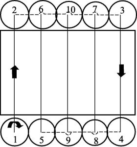
Figure 3-12 illustrates the sequence and methods of all tool movements. The idea behind this method is to keep the width of each cut roughly the same. At any given time, only about 2/3 of the diameter is involved in the cutting, and it is always in the conventional milling mode.
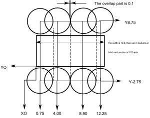
Example: Based on Figure 3-13, write the program.
O2802
N1 G20 (Imperial Units)
N2 G17 G40 G80
N3 G90 G54 G00 X0.75 Y-2.75 S344 M03 (Position 1)
N4 G43 Z1.0 H01
N5 G01 Z-0.2 F50.0 M08 (Milling Depth 0.2)
N6 Y8.75 F21.0 (Position 2)
N7 G00 X12.25 (Position 3)
N8 G01 Y-2.75 (Position 4)
N9 G00 X4.0 (Position 5)
N10 G01 Y8.75 (Position 6)
N11 G00 X8.9 (Position 7, Overhang on both sides 0.1)
N12 G01 Y-2.75 (Position 8, End)
N13 G00 Z1.0 M09
N14 G91 G28 X0 Y0 Z0
N15 M05
N16 M30
The example above could choose to process along the X-axis direction to shorten the program, but for the sake of illustration, the Y-axis is more convenient.
4 Processing Example
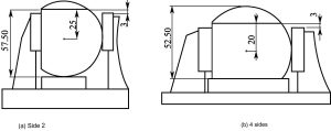
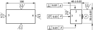
As shown in Figure 3-14, the part is made of 45 steel, the blank is round steel, and there are no heat treatment and hardness requirements.
(1) Process Analysis
The process analysis of the flat part is as follows:
- Reference Plane: Plane 1 is the design reference. Planes 2 and 4 have perpendicularity requirements with Plane 1, and Plane 3 has parallelism requirements with Plane 1. To ensure perpendicularity and parallelism, Plane 1 is always the primary positioning reference when clamping the workpiece with a vise. Plane 1 also serves as the reference for measuring perpendicularity and parallelism, aligning the design, manufacturing, and measurement references.
- Selection of Blank Round Steel Diameter: According to the Pythagorean theorem, as shown in Figure 3-15, the diameter ϕD of the round steel can be calculated. Based on the calculation, the closest size to ϕD (64.03) is ϕ65, so the diameter of the blank round steel is chosen as ϕ65.
-
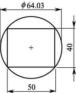
Figure 3-15 Calculation of diameter of round steel material - Processing Steps: The processing steps for the flat part shown in Figure 3-14 are listed in Table 3-1.
-
No. Name Material Hardness Flute Helix Angle Work Material Notes 1 Straight shank Φ100 High-speed steel High High N/A Steel N/A 2 Ball-end mill, 1 flute Tungsten carbide Medium φ60mm N/A Cast Iron Suitable for engraving, good wear resistance 3 Ball-end mill, 2 flutes Tungsten carbide Medium φ60mm Low Non-ferrous metals Suitable for processing, smooth surface 4 Ball-end mill, 4 flutes Tungsten carbide Medium φ60mm 25°~50° Cast Iron Suitable for processing, high efficiency 5 Ball-end mill, 3 flutes Tungsten carbide Medium φ60mm 25°~50° Non-ferrous metals High cutting efficiency, good surface quality
Table 3-1
- Tool and Cutting Amount Selection: The type of tool is determined based on the characteristics of the part being processed. Since the surface being processed is wide, a face mill is used. The material of the indexable insert is chosen from the YT series. The diameter of the face mill is determined by calculating the maximum width of the surface being processed. The maximum width is determined on processing surfaces 1 and 3, as shown in Figure 3-16. The maximum width can be determined using the Pythagorean theorem, and the calculated result is 51.23. The diameter of the face mill is chosen as ϕ60.
-
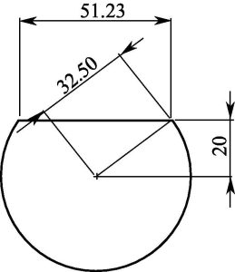
Figure 3-16 Maximum processing plane width
When processing 1 plane, the milling machining allowance is relatively large, the thickness is 32.5-20=12.5, and layered milling is required. According to the selection principle of cutting amount, first select the back cutting amount, then select the feed speed, and finally consider the tool cutting speed. The final cutting amount is shown in Table 3-2. Table 3-2 only lists the cutting amounts for processing plane 1. The cutting amounts for other planes are basically the same as plane 1, so they are not listed here one by one.
| Processing Material | Tool Material | Number of Edges | Spindle Speed (r/min) | Cutting Depth (mm) | Feed Rate (mm/min) |
| Cast Iron | Tungsten carbide | 4 | 500 | 6.5 | 160 |
| Cast Iron | High-speed steel | 4 | 500 | 5.5 | 160 |
| Cast Iron | High-speed steel | 4 | 800 | 0.5 | 160 |
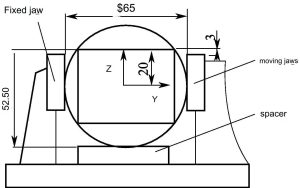
(2) Clamping Method and Positioning Reference
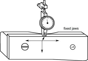
The workpiece is positioned by the fixed jaw and the pad. The moving jaw clamps the workpiece. The thickness of the pad should ensure that the distance between the processed surface and the jaw is 3mm, as shown in Figure 3-17. The fixed jaw of the vise needs to be inspected, as shown in Figure 3-18, to ensure the perpendicularity and parallelism of the fixed jaw with the worktable.
(3) Toolpath
This part is produced as a single piece. The origin of the workpiece coordinate system is set at the center of the workpiece, and the X-axis is set on the axis, as shown in Figure 3-17. The processing is divided into two roughing operations and one finishing operation. To improve processing efficiency, the tool is inserted from both sides of the workpiece; to shorten the processing program, subprograms are called.
(4) Programming
O0001
N100 G21
N102 G0 G17 G40 G49 G80 G90
N104 M8 ; Coolant On
N108 G0 G90 G54 X-85. Y0. S350 M3 ; Lead-in length + Cutting direction overhang = 35
N110 G43 H1 Z100. ; Safe Height
N112 Z35.5 ; 3mm above the raw material surface
N114 G1 Z26. F200. ; Milling depth is 6.5
N116 M98 P1001 ; Call Subprogram
N118 G90 Z20.5 F200.
N120 M98 P1002
N122 G90 Z20. F200.
N124 M98 P1001
N142 G0 G90 Z100.
N144 M9 ; Coolant Off
N146 M5 ; Spindle Stop
N148 G91 G28 Z0.
N150 G28 X0. Y0.
N152 M30 ; End of Program
Subprogram (Milling from -X direction to +X direction):
O1001
N100 G91
N102 X170. F120. ; Lead-out length + Cutting direction overhang = 35
N104 M99 ; End of Subprogram
Subprogram (Milling from +X direction to -X direction):
O1002
N100 G91
N102 X-170. F120.
N104 M99 ; End of Subprogram
Tips: To reduce the tool path, cut from both sides of the workpiece. During rough and finish milling, the milling cutter needs to completely mill out the workpiece.
(5) Milling of Faces 2, 3, and 4:
The clamping for milling faces 2 and 4 is shown in Figure 3-19 and is basically the same as for face 1. Since there are already machined faces, special attention needs to be paid to determining which face is the primary locating face and which one is the secondary locating face.