E-Mail:sales@whalescnc.com
E-Mail:sales@whalescnc.com
Surface roughness is a very important concept. This article takes “surface roughness” as the central concept and introduces the evaluation basis, evaluation parameters and other issues in detail. It is worth reading! There is also a question about surface roughness 100, which is explained clearly.
1. The concept of surface roughness
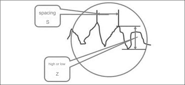
Surface roughness refers to the unevenness of the machined surface with small spacing and tiny peaks and valleys. The distance (wave pitch) between the two wave crests or two wave troughs is very small (less than 1mm), which is a microscopic geometric shape error.
Specifically refers to the height and spacing S of small peaks and valleys. Generally divided into S points:
- S<1mm is surface roughness;
- 1≤S≤10mm is waviness;
- S>10mm is f shape.
2. VDI3400, Ra, Rmax Comparison table
National standards stipulate that three indicators are commonly used to evaluate surface roughness (unit: μm): the average arithmetic deviation Ra of the profile, the average height of unevenness Rz, and the maximum height Ry. The Ra indicator is often used in actual production. The maximum microscopic height deviation Ry of the contour is commonly expressed by the Rmax symbol in Japan and other countries, and the VDI indicator is commonly used in Europe and the United States. The following is a comparison table of VDI3400, Ra and Rmax.
VDI3400, Ra, Rmax Comparison table
|
|
|
|
|
|
|
|
|
|
|
|
|
|
|
|
|
|
|
|
|
|
|
|
|
|
|
|
|
|
|
|
|
|
|
|
|
|
|
|
|
|
|
|
|
|
|
|
3. Factors causing surface roughness
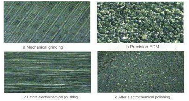
Surface roughness is generally caused by the processing method used and other factors, such as the friction between the tool and the part surface during the processing process, the plastic deformation of the surface metal during chip separation, and high-frequency vibration in the process system, electrical machining discharge pits, etc. Due to different processing methods and workpiece materials, the depth, density, shape and texture of the marks left on the processed surface are different.
4. The main effects of surface roughness on parts
Affect wear resistance.The rougher the surface, the smaller the effective contact area between mating surfaces, the greater the pressure, the greater the friction resistance, and the faster the wear.
Affects the stability of the fit. For clearance fits, the rougher the surface, the easier it is to wear, causing the gap to gradually increase during work; for interference fits, the actual effective interference is reduced due to the flattening of microscopic convex peaks during assembly. the connection strength.
Affects fatigue strength. There are large troughs on the surface of rough parts, which, like sharp corners and cracks, are sensitive to stress concentration, thus affecting the fatigue strength of the part.
Affects corrosion resistance. Rough parts surfaces can easily allow corrosive gases or liquids to penetrate into the inner metal layer through microscopic valleys on the surface, causing surface corrosion.
Affect sealing. Rough surfaces cannot fit tightly together, and gas or liquid leaks through the gaps between the contact surfaces.
Affects contact stiffness. Contact stiffness is the ability of the joint surface of parts to resist contact deformation under the action of external forces. The stiffness of a machine depends largely on the stiffness of the contact between the various parts.
Affect the measurement accuracy. The surface roughness of the measured surface of the part and the measuring surface of the measuring tool will directly affect the accuracy of the measurement, especially in precision measurement.
In addition, surface roughness will have varying degrees of impact on the parts’ coating, thermal conductivity and contact resistance, reflective ability and radiation performance, resistance to liquid and gas flow, and conductor surface current flow.
5. Basis for surface roughness evaluation
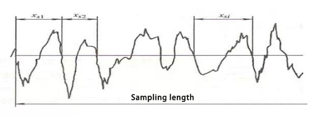
①. Sampling length
The sampling length is a reference line length specified for evaluating surface roughness. The length that can reflect the surface roughness characteristics should be selected based on the actual surface formation and texture characteristics of the part. The sampling length should be measured based on the general direction of the actual surface profile. The sampling length is specified and selected in order to limit and reduce the effects of surface waviness and shape errors on the surface roughness measurement results.
②. Assessment length
The evaluation length is a length necessary to evaluate the profile, which may include one or several sampling lengths. Since the surface roughness of various parts of the part surface is not necessarily uniform, one sampling length often cannot reasonably reflect a certain surface roughness feature. Therefore, several sampling lengths need to be taken on the surface to evaluate the surface roughness. The evaluation length generally includes 5 sampling lengths.
③. Baseline
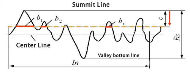
The reference line is the contour center line used to evaluate surface roughness parameters. There are two types of baselines: the least squares midline of the contour: within the sampling length, the sum of squares of the contour offsets of each point on the contour is the smallest, and it has a geometric contour shape. Arithmetic mean center line of the contour: Within the sampling length, the areas of the contours on both sides of the center line are equal. Theoretically, the least squares center line is the ideal baseline, but it is difficult to obtain in practical applications. Therefore, the arithmetic mean center line of the contour is generally used instead, and a straight line with an approximate position can be used instead during measurement.
6. Surface roughness evaluation parameters
①. Height characteristic parameters
Ra arithmetic mean deviation of the contour: the arithmetic mean of the absolute value of the contour deviation within the sampling length (lr). In actual measurement, the greater the number of measurement points, the more accurate Ra is. Rz maximum height of the profile: the distance between the peak line and the bottom line of the valley.
Ra is preferred within the common range of amplitude parameters. Before 2006, there was an evaluation parameter in the national standard: “The ten-point height of microscopic unevenness”, which is represented by Rz, and the maximum height of the profile is represented by Ry. After 2006, the ten-point height of microscopic unevenness was canceled in the national standard, and Rz was adopted. Indicates the maximum height of the profile.
②. Spacing characteristic parameters
Rsm Average width of contour cells. The average spacing of microscopic irregularities in the profile within the sampling length. The micro-irregularity spacing refers to the length of the contour peak and the adjacent contour valley on the center line. For the same Ra value, the Rsm value is not necessarily the same, so the reflected texture will be different. Surfaces that value texture usually focus on the two indicators of Ra and Rsm.
The Rmr shape characteristic parameter is expressed by the profile support length ratio, which is the ratio of the profile support length to the sampling length. The contour support length is the sum of the lengths of the sections obtained by intersecting the contour with a straight line parallel to the center line and distance c from the contour peak line within the sampling length.
7. Surface roughness measurement method
①. Comparative method
Used for on-site measurements in workshops, often used for measurements on medium or rough surfaces. The method is to determine the roughness value of the measured surface by comparing it with a roughness sample marked with a certain value.
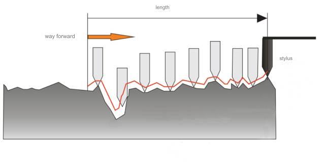
②. Stylus method
Surface roughness uses a diamond stylus with a tip radius of curvature of about 2 microns to slowly slide along the measured surface. The up and down displacement of the diamond stylus is converted into an electrical signal by an electrical length sensor. After amplification, filtering and calculation, it is indicated by a display instrument. To obtain the surface roughness value, a recorder can also be used to record the profile curve of the measured section. Generally, measuring tools that can only display surface roughness values are called surface roughness measuring instruments, while those that can record surface profile curves are called surface roughness profile meters. Both measuring tools have electronic calculation circuits or computers, which can automatically calculate the arithmetic mean deviation of the profile Ra, the ten-point height of micro-irregularity Rz, the maximum height of the profile Ry and other various evaluation parameters. They have high measurement efficiency and are suitable for Measure the surface roughness with Ra ranging from 0.025 to 6.3 microns.
100 Questions and Answers on Surface Roughness, Don’t Think It’s Simple!
1. What is surface roughness?
Answer: Surface roughness refers to the micro-geometric features consisting of small spacing and peaks and valleys on the machined surface of the part. It is a microscopic geometric shape error.
2. How does surface roughness occur?
Answer: The surface of parts formed by cutting or other methods always has geometric errors due to plastic deformation of the material during processing, mechanical vibration, friction and other reasons.
3. What effect does surface roughness have on parts?
Answer: Surface roughness has an important impact on the friction and wear of parts, fatigue strength, corrosion resistance and the matching properties between parts.
4. What are the main national standards for “surface roughness” in my country at present?
Answer: GB/T 3505 2000 Surface roughness terminology surface and its parameters; GB/T 1031-1995 Surface roughness parameters and their numerical values; GB/T 131-1993 Mechanical drawing surface roughness symbols, codes and their notation methods.
5.What is called actual contour?
Answer: It is the contour line obtained by the intersection of the plane and the actual surface. According to the different intersecting directions, it can be divided into transverse actual contour and longitudinal actual contour. When evaluating and measuring surface roughness, unless otherwise specified, the actual transverse profile is usually used, that is, the profile on the cross-section perpendicular to the direction of the processed grain.
6. What is the sampling length?
Answer: It is used to identify the length of a reference line with surface roughness characteristics. The rougher the surface, the greater the sampling length should be. The sampling length is specified in order to limit and weaken the influence of other geometric errors on the surface roughness measurement results. Within the sampling length range, it generally includes more than 5 contour peaks and contour valleys. For the selection value of the sampling length, please refer to GB/T 1031-1995 Surface roughness parameters and their values.
7. What is the assessment length?
Answer: It is a length necessary to evaluate the contour, which can include one or several sampling lengths. Due to the uneven surface processing of parts, in order to fully and reasonably reflect the roughness characteristics of the measured surface, several sampling lengths need to be used for evaluation. For the selection value of the evaluation length, please refer to GB/T 1031-1995 Surface roughness parameters and their numerical values.
8. What is a baseline?
Answer: A reference line for evaluating the numerical value of surface roughness parameters is called the baseline. There are two types of baselines: the contour least squares midline and the contour arithmetic mean midline.
9. What is called the contour least squares midline?
Answer: The least squares midline of the contour is the line that minimizes the sum of squares of the contour offsets of each point on the contour within the sampling length.
10.What is called the arithmetic mean midline of the contour?
Answer: The arithmetic mean center line of the contour is the line that divides the actual contour into upper and lower parts within the sampling length and makes the upper and lower areas equal.
11.What are the basic evaluation parameters?
Answer: The three height parameters are the basic evaluation parameters, namely the arithmetic mean deviation of the profile (Ra), the ten-point height of the micro-roughness (Rz) and the maximum height of the profile (Ry); the other three are additional evaluation parameters, namely the micro-roughness of the profile The average spacing (Sm), the average spacing of the single peak of the profile (S) and the profile support length ratio (tP).
12. What is called the contour arithmetic mean deviation (Ra)?
Answer: Within the sampling length, the arithmetic mean of the absolute value of the distance from each point on the measured contour to the contour centerline. The larger the Ra value, the rougher the surface. Ra can objectively reflect the geometric characteristics of the measured contour. The Ra value can be directly measured with an electric profilometer, but it is not intuitive enough.
13.What is the ten-point height of micro-roughness (Rz)?
Answer: Within the sampling length, the sum of the average of the five largest contour peak heights and the average of the five largest valley depths. The larger the Rz value, the rougher the surface. Rz is highly intuitive for evaluating surface roughness height parameters and is easy to measure on optical instruments, but it has limitations in reflecting the geometric shape characteristics of the measured contour.
14.What is called the maximum height of the profile (Ry)?
Answer: The distance between the peak line and the bottom line of the valley within the sampling length. The peak line and valley bottom line refer to the lines parallel to the midline and passing through the highest and lowest points of the contour within the sampling length, respectively. The parameter Ry is simple to measure. When the surface to be measured is small and it is not suitable to use Rz, Rz evaluation can be used.
15. How to determine the allowable values of surface roughness height evaluation parameters (Ra, Rz, Ry)?
Answer: See GB/T 1031-1995 surface roughness parameters and their values.
16. When the symbol and code of surface roughness is ![]() , what is its meaning?
, what is its meaning?
Answer: Basic symbols and surface representations can be obtained by any method. When no roughness parameter value or relevant description (such as surface treatment, local heat treatment conditions, etc.) is added, only simplified code labeling is applicable.
17. When the symbol and code of surface roughness is ![]() , what is its meaning?
, what is its meaning?
Answer: The basic symbol plus a dash indicates that the surface is obtained by removing material. For example: turning, milling, drilling, grinding, shearing, polishing, corrosion, EDM, gas cutting, etc.
18. When the symbol and code of surface roughness is ![]() , what is its meaning?
, what is its meaning?
Answer: A small circle is added to the basic symbol to indicate that the surface is obtained without removing material. For example: casting, forging, stamping deformation, hot rolling, cold rolling, powder metallurgy, etc. Or a surface used to maintain the original supply condition (including maintaining the condition of the previous process).
19. When the symbol and code of surface roughness is ![]() , what is its meaning?
, what is its meaning?
Answer: The upper limit of Ra is 3.2μm for surface roughness obtained by any method.
20. When the symbol and code of surface roughness is ![]() , what is its meaning?
, what is its meaning?
Answer: The upper limit of Ra is 3.2μm for the surface roughness obtained by removing material.
21. When the symbol and code of surface roughness is ![]() , what is its meaning?
, what is its meaning?
Answer: The upper limit of Ra is 3.2μm for surface roughness obtained without material removal.
22. When the symbol and code name of surface roughness is ![]() , what is its meaning?
, what is its meaning?
Answer: For the surface roughness obtained by removing material, the upper limit of Ra is 3.2 μm and the lower limit of Ra is 1.6 μm.
23. When the symbol and code of surface roughness is ![]() , what is its meaning?
, what is its meaning?
Answer: The upper limit of Ry is 3.2μm for the surface roughness obtained by any servo method.
24. When the symbol and code of surface roughness is ![]() , what is its meaning?
, what is its meaning?
Answer: The upper limit of Rz is 200μm for surface roughness obtained without material removal.
25. When the symbol and code of surface roughness is ![]() , what is its meaning?
, what is its meaning?
Answer: The upper limit of Rz is 3.2μm and the lower limit of Rz is 1.6μm for the surface roughness obtained by removing material.
26. When the symbol and code of surface roughness is ![]() , what is its meaning?
, what is its meaning?
Answer: For the surface roughness obtained by removing material, the upper limit of Ry is 3.2 μm and the lower limit of Ry is 12.5 μm.
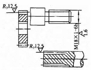
27. What should we pay attention to when marking surface roughness?
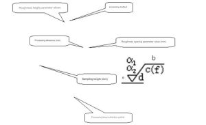
Answer: When Ra is selected as the height parameter, its code name can be omitted when labeling. When Ry and Rz are selected, the code name cannot be omitted. The surface roughness code given on the drawing is the requirement for the finished surface. Generally, you only need to indicate the symbol and the allowable parameter value. If there are special requirements for the surface function of the part (additional requirements such as processing texture, processing allowance, etc.), relevant parameters or codes can be marked around the basic symbols.
28. How to draw the surface roughness symbol?
Answer: As shown in Figure 1.
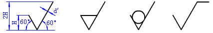
d‘ =h/10;H=1.4h;h is the font height.
29.What are the methods for labeling surface roughness? Example 1.
Answer: As shown in Figure 2.
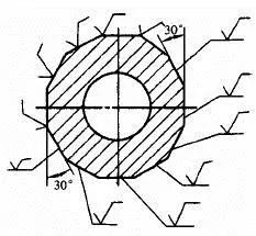
The surface roughness code (symbol) should be noted on the visible contour lines, dimension lines, extension lines or their extension lines. The tip of the symbol must point away from the material toward the surface.
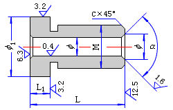
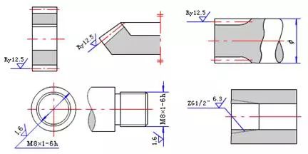
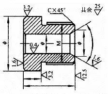
30. What are the methods for marking surface roughness? Example 2.
Answer: As shown in Figure 3.
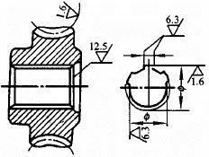
The center hole working surface, keyway working surface, chamfer, and rounded surface can simplify marking.
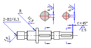
31.What are the methods for marking surface roughness? Example 3.
Answer: As shown in Figure 4.
The marking method when the tooth (tooth) shape is not drawn on the working surfaces of gears, involute splines, threads, etc.32. What are the methods for labeling surface roughness? Example 4.
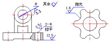
Answer: As shown in Figure 5.
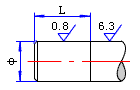
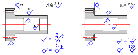
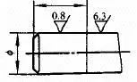
When the same surface has different surface roughness requirements, the dividing line must be drawn with a thin solid line, and the corresponding surface roughness symbol and size must be noted
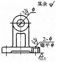
33. What are the methods for labeling surface roughness? Example 5.
Answer: As shown in Figure 6.
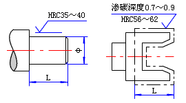
When it is necessary to indicate local heat treatment or local plating, the range should be drawn with thick dotted lines and the corresponding dimensions should be marked. The requirements can also be written in the surface roughness symbol.34. What are the methods for marking surface roughness? Example 6.
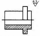
Answer: As shown in Figure 7.
The continuous surface of the part and the surface of repeated elements (holes, grooves, teeth, etc.) and the discontinuous surface connected by thin solid lines, their symbols (symbols) are marked only once.35.What are the methods for marking surface roughness? Example 7.
Answer: As shown in Figure 8.
When most of the parts have the same surface requirements, they should be marked uniformly in the upper right corner and add the word “rest”. In order to simplify the annotation, or when the location is restricted, simplified codes can be marked, or omissions can be used, but the meaning of these simplified codes (symbols) must be explained near the title bar. When using unified labeling and simplified labeling, the codes and text descriptions should be 1.4 times the codes and text noted on other surfaces on the graphic.
36. How to determine the location of surface roughness parameters and various regulations?
Answer: As shown in Figure 9.
37. How to choose surface roughness?
Answer: The selection of surface roughness must not only meet the functional requirements of the part surface, but also consider the economy of processing.
38. When using the analogy method to determine surface roughness, what are the general principles for selecting height parameters?
Answer: On the same part, the surface roughness value of the working surface should be smaller than that of the non-working surface. The surface roughness value of the friction surface should be smaller than the non-friction surface; the surface roughness value of the rolling friction surface should be smaller than the sliding friction surface; the surface roughness value of high movement speed and large unit pressure should be small. The surface roughness value of the surface subject to cyclic load and the parts easily causing stress concentration (such as fillets and grooves) should be selected smaller. Combining surfaces with high requirements for mating properties, mating surfaces with small mating gaps, and interference mating surfaces that require reliable connections and are subject to heavy loads should all have smaller surface roughness values. With the same fit properties, the smaller the size of the part, the smaller its surface roughness value should be. For the same accuracy level, the surface roughness value of small size and shaft is smaller than that of large size and hole. For the mating surface, its dimensional tolerance, shape tolerance, and surface roughness should be coordinated, and generally there is a certain corresponding relationship.
39. When the surface roughness Ra is 50~100μm, what are the characteristics of the surface shape and how to apply it?
Answer: The surface shape is characterized by obvious tool marks. It is used on rough machined surfaces and is generally rarely used. Casting, forging and gas cutting blanks can meet this requirement.
40. When the surface roughness Ra is 25μm, what are the characteristics of the surface shape and how to apply it?
Answer: The surface shape is characterized by visible tool marks, which is applied to rough machined surfaces and is generally rarely used. Casting, forging and gas cutting blanks can meet this requirement.
41. When the surface roughness Ra is 12.5μm, what are the characteristics of the surface shape and how to apply it?
Answer: The surface shape is characterized by micro knife marks. It is used in the first level of rough machining, which has a wide range of applications, such as shaft end surfaces, chamfers, surfaces of screw holes and rivet holes, contact surfaces of washers, etc.
42. When the surface roughness Ra is 6.3μm, what are the characteristics of the surface shape and how to apply it?
Answer: Surface shape features are visible machining marks, which are applied to semi-rough machined surfaces, non-contact free surfaces such as brackets, boxes, clutches, pulley sides, cam sides, surfaces in contact with bolt heads and rivet heads, all shafts and The undercut of the hole, the joint surface of the general cover, etc.
43. When the surface roughness Ra is 3.2μm, what are the characteristics of the surface shape and how to apply it?
Answer: The surface shape is characterized by micro machining marks. It is applied to semi-finished surfaces, surfaces such as boxes, brackets, covers, sleeves, etc. that are connected to other parts without matching requirements, surfaces that need to be blue, and knurling. Pre-machined surfaces, all non-contact outer surfaces of the spindle, etc. It is a surface roughness value that can be achieved more economically by basic cutting processing methods such as turning.
44. When the surface roughness Ra is 1.6μm, what are the characteristics of the surface shape and how to apply it?
Answer: The surface shape is characterized by unclear processing marks. It is used for surfaces with high surface quality requirements, medium-sized machine tool worktables (ordinary precision), combined machine tool spindle boxes and cover surfaces, medium-sized flat pulleys and triangle pulleys. The working surface, the pressing hole of the bushing sliding bearing, and the journal that generally rotates at low speed. Non-fitting surfaces of some important parts of aviation and aerospace products.
45. When the surface roughness Ra is 0.8μm, what are the characteristics of the surface shape and how to apply it?
Answer: The surface shape feature is the direction in which machining traces can be discerned. It is used in medium-sized machine tools (normal precision) sliding guide surfaces, guide rail pressure plates, surfaces of cylindrical pins and conical pins, general precision dials, and outer surfaces that require chrome plating and polishing. Rapidly rotating journal, positioning pin press-in hole, etc. It is a commonly used value for mating surfaces and is an important mating point for medium and heavy equipment. It is economical to grind.
46. When the surface roughness Ra is 0.4μm, what are the characteristics of the surface shape and how to apply it?
Answer: The surface shape feature is the direction of micro-discrimination of machining marks, which is used in medium-sized machine tools (to improve accuracy) sliding guide surfaces, working surfaces of sliding bearings, main surfaces of fixture positioning elements and drill bushings, working journals of crankshafts and camshafts, The surface of the indexing plate, the working surface of the journal and bushing under high-speed operation, etc.
47. When the surface roughness Ra is 0.2μm, what are the characteristics of the surface shape and how to apply it?
Answer: The surface shape is characterized by the direction of indiscernible machining traces. It is used in precision machine tool spindle taper holes and apex conical surfaces; the joint surface of small-diameter precision mandrels and rotating shafts, and the piston pin holes of pistons, which require airtight surfaces and supports. The surface, the leaf basin and the back surface of the aero-engine blade.
48. When the surface roughness Ra is 0.1μm, what are the characteristics of the surface shape and how to apply it?
Answer: The surface shape is characterized by a dark glossy surface. It is used in the holes where the main spindle box of precision machine tools matches the sleeve. The surfaces that the instrument must bear friction during use, such as guide rails, groove surfaces, etc., the surface of holes used for hydraulic transmission, and valves. Working surface, cylinder inner surface, piston pin surface, etc. General mechanical design limits. Grinding is very uneconomical.
49. When the surface roughness Ra is 0.05μm, what are the characteristics of the surface shape and how to apply it?
Answer: The surface shape is characterized by a bright glossy surface, which is used in particularly precise rolling bearing ring raceways, ball and roller surfaces, working surfaces of medium-precision clearance fitting parts in measuring instruments, measuring surfaces of working gauges, etc.
50. When the surface roughness Ra is 0.025μm, what are the characteristics of the surface shape and how to apply it?
Answer: The surface shape is characterized by a mirror-like glossy surface, which is used in particularly precise rolling bearing ring raceways, balls and roller surfaces, and the mating surfaces of plungers and plunger sleeves in high-pressure oil pumps to ensure a highly airtight bonding surface, etc.
51. When the surface roughness Ra is 0.012μm, what are the characteristics of the surface shape and how to apply it?
Answer: The surface shape feature is a foggy mirror surface, which is applied to the measuring surface of instruments, the working surface of high-precision clearance fit parts in measuring instruments, the working surface of gauge blocks with a size exceeding 100mm, etc.
52. When the surface roughness Ra is 0.008μm, what are the characteristics of the surface shape and how to apply it?
Answer: The surface shape feature is mirror surface, which is used in the working surface of gauge blocks, the measuring surface of high-precision measuring instruments, and the metal mirror surface in optical measuring instruments, etc.
53. When the surface roughness Ra is >10~40μm, what are the economical processing methods?
Answer: The economical processing methods are rough turning, rough planing, rough milling, drilling, rasping, and sawing.
54. When the surface roughness Ra is >5~10μm, what are the economical processing methods?
Answer: The economical processing methods are turning, planing, milling, boring, drilling and rough reaming.
55. When the surface roughness Ra is >2.5~5μm, what are the economical processing methods?
Answer: The economical processing methods are turning, planing, milling, boring, grinding, drawing, rough scraping and rolling.
56. When the surface roughness Ra is >1.25~2.5μm, what are the economical processing methods?
Answer: The economical processing methods are turning, planing, milling, boring, grinding, drawing, scraping, pressing and tooth milling.
57. When the surface roughness Ra is >0.63~1.25μm, what are the economical processing methods?
Answer: The economical processing methods are turning, boring, grinding, drawing, scraping, fine reaming, gear grinding, and rolling.
58. When the surface roughness Ra is >0.32~0.63μm, what are the economical processing methods?
Answer: The economical processing methods are fine reaming, fine boring, grinding, scraping and rolling.
59. When the surface roughness Ra is >0.16~0.32μm, what are the economical processing methods?
Answer: The economical processing methods are fine grinding, honing, grinding and super-finishing.
60. When the surface roughness Ra is >0.08~0.16μm, what are the economical processing methods?
Answer: The economical processing methods are fine grinding, grinding and ordinary polishing.
61. When the surface roughness Ra is >0.01-0.08μm, what are the economical processing methods?
Answer: The economical processing methods are super fine grinding, fine polishing and mirror grinding.
62. When the surface roughness Ra is ≤0.01μm, what are the economical processing methods?
Answer: The economical processing methods are mirror grinding and super precision grinding.
63. How to choose the thread surface roughness parameter value Ra?
Answer: When the accuracy level of coarse thread ordinary thread is level 4, Ra is 0.4~0.8μm.
When the accuracy level of coarse thread ordinary thread is level 5, Ra is 0.8μm.
When the precision grade of coarse thread ordinary thread is level 6, Ra is 1.6~3.2μm.
When the accuracy level of fine-thread ordinary thread is level 4, Ra is 0.2~0.4μm.
When the accuracy level of fine-thread ordinary thread is level 5, Ra is 0.8μm.
When the accuracy level of fine-thread ordinary thread is level 6, Ra is 1.6~3.2μm.
64. How to choose the bond surface roughness parameter value Ra?
Answer: The bonding form is a key, and when moving along the hub groove, Ra is 0.2~0.5μm.
The bonding form is a key, and when moving along the axis groove, Ra is 0.2~0.4μm.
The bonding form is a bond, and the fixed position, Ra is 1.6μm.
The combination form is a shaft groove. Where it moves along the hub groove, Ra is 1.6μm.
The combination form is an axis groove, and when moving along the axis groove, Ra is 0.4~0.8μm.
The combination form is a shaft groove, and the fixed position, Ra is 1.6μm.
The combination form is a hub groove. Where it moves along the hub groove, Ra is 0.4~0.8μm.
The combination form is a hub groove. Where it moves along the shaft groove, Ra is 1.0μm.
The combination form is hub groove, and the fixed position, Ra is 1.6~3.2μm.
Note: The non-working surface Ra is 6.3μm.
65. How to choose the surface roughness parameter value Ra of rectangular spline?
Answer: Internal spline, at the outer diameter, Ra is 6.3μm.
Internal spline, inner diameter, Ra is 0.8μm.
Internal spline, key side, Ra is 3.2μm.
External splines, at the outer diameter, Ra is 3.2μm.
External spline, inner diameter, Ra is 0.8μm.
External spline, key side, Ra is 0.8μm.
66. How to choose the gear surface roughness parameter value Ra?
Answer: When the part is the tooth surface and the accuracy level is level 5, Ra is 0.2~0.4μm.
When the tooth surface accuracy level is level 6, Ra is 0.4μm.
When the tooth surface accuracy level is level 7, Ra is 0.4~0.8μm.
When the tooth surface accuracy level is 8, Ra is 1.6μm.
When the tooth surface accuracy level is level 9, Ra is 3.2μm.
When the tooth surface accuracy level is level 10, Ra is 6.3μm.
When the part is an outer circle and the accuracy level is level 5, Ra is 0.8~1.6μm.
When the part is an outer circle and the accuracy level is level 6, Ra is 1.6~3.2μm.
When the part is an outer circle and the accuracy level is level 7, Ra is 1.6~3.2μm.
When the part is an outer circle and the accuracy level is level 8, Ra is 1.6~3.2μm.
When the part is an outer circle and the accuracy level is level 9, Ra is 3.2~6.3μm.
When the part is an outer circle and the accuracy level is level 10, Ra is 3.2~6.3μm.
When the end face accuracy level is level 5, Ra is 0.4~0.8μm.
When the end face accuracy level is level 6, Ra is 0.4~0.8μm.
When the end face accuracy level is level 7, Ra is 0.8~3.2μm.
When the end face accuracy level is level 8, Ra is 0.8~3.2μm.
When the end face accuracy level is level 9, Ra is 3.2~6.3μm.
When the end face accuracy level is level 10, Ra is 3.2~6.3μm.
67 How to choose the surface roughness parameter value Ra of worm gear?
Answer: When the worm part is the tooth surface and the accuracy level is level 5, Ra is 0.2μm.
When the worm part is a tooth surface with an accuracy level of 6, Ra is 0.4 μm.
When the worm part is a tooth surface with an accuracy level of 7, Ra is 0.4 μm.
When the worm part is a tooth surface with an accuracy level of 8, Ra is 0.8 μm.
When the worm part is a tooth surface with an accuracy level of 9, Ra is 1.6 μm.
When the worm part is the tooth tip and the accuracy level is level 5, Ra is 0.2μm.
When the worm part is the tooth tip and the accuracy level is level 6, Ra is 0.4μm.
When the worm part is the tooth tip and the accuracy level is level 7, Ra is 0.4μm.
When the worm part is the tooth tip and the accuracy level is level 8, Ra is 0.8μm.
When the worm part is the tooth tip and the accuracy level is level 9, Ra is 1.6 μm.
Note: The worm part is the tooth root, and Ra is 6.3μm.
When the worm gear part is a tooth surface with an accuracy level of 5, Ra is 0.4 μm.
When the tooth surface accuracy level of the worm gear is level 6, Ra is 0.4μm.
When the worm gear part is a tooth surface with an accuracy level of 7, Ra is 0.8 μm.
When the worm gear part is a tooth surface with an accuracy level of 8, Ra is 1.6 μm.
When the worm gear part is a tooth surface with an accuracy level of 9, Ra is 3.2 μm.
Note: The worm gear part is the tooth root, and Ra is 3.2μm.
68. How to choose the sprocket surface roughness parameter value Ra?
Answer: When the working surface precision of the sprocket teeth is average, Ra is 1.6~3.2μm.
When the working surface of the sprocket teeth has high precision, Ra is 0.8~1.6μm.
When the tooth base is of average accuracy, Ra is 3.2μm.
When the location is the tooth base with high accuracy, Ra is 1.6μm.
When the tooth top accuracy is average, Ra is 1.6~3.2μm.
When the part is a tooth tip with high precision, Ra is 1.6~6.3μm.
69. How to choose the pulley surface roughness parameter value Ra?
Answer: The location is the working surface of the pulley. When the pulley diameter is ≤120mm, Ra is 0.8μm.
When the pulley diameter is ≤300mm on the working surface of the pulley, Ra is 1.6μm.
When the pulley diameter is greater than 300mm on the working surface of the pulley, Ra is 3.2μm.
70. How to choose the surface roughness parameter value Ra of hydraulic components?
Answer: The part is the piston pump crank. At the piston, Ra is 1.6~0.8μm.
The parts are connecting rod journal, bearing bush, and center journal. Ra is 0.4μm.
The location is the outer cylindrical surface of the piston. At the side surface, Ra is 0.8μm.
The parts are the connecting rod hole of the piston pump, the cylinder barrel, the slide valve bushing, the plunger, and the piston. Ra is 0.8~0.4μm.
The parts are slide valve, high-pressure pump plunger valve, and valve seat. Ra is 0.2~0.1μm.
71. How to choose the surface roughness parameter Ra of the mating surface of the sliding bearing?
Answer: The location is the shaft tolerance level IT7-IT9, Ra is 0.2~3.2μm.
The location is the shaft tolerance level IT11-IT12, Ra is 1.6~3.2μm.
The location is hole tolerance level IT7-IT9, Ra is 0.4~1.6μm.
The location is hole tolerance level IT11-IT12, Ra is 1.6~3.2μm.
72. How to choose the conical combined surface roughness parameter value Ra?
Answer: The location is the sealing joint of the outer cone surface, Ra is ≤0.1μm.
The location is the centering joint of the outer cone surface, Ra is ≤0.2μm.
The location is other joints on the outer cone surface, Ra is ≤1.6~3.2μm.
The location is the sealing joint of the inner cone surface, Ra is ≤0.2μm.
The location is the centering joint of the inner cone surface, Ra is ≤0.8μm.
The location is other joints on the inner cone surface, Ra is ≤1.6~3.2μm.
73.What are the methods for labeling surface roughness? Specification 1.
Answer: The direction of the numbers and symbols in the surface roughness code must be marked as specified in the figure below. As shown in Figure 10.
74.What are the methods for labeling surface roughness? Specification 2.
Answer: Surface roughness symbols with horizontal lines should be marked as shown below. See Figure 11.
75.What are the methods for labeling surface roughness? Specification 3.
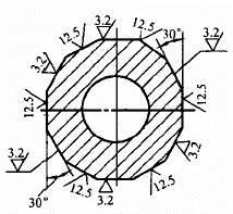
Answer: The tip of the symbol must point from the outside of the material to the surface. The most commonly used roughness code is uniformly noted in the upper right corner of the drawing, with the word “rest” in front. As shown in Figure 12.
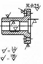
76.What are the methods for labeling surface roughness? Specification 4.
Answer: When all surface roughness requirements are the same, they can be uniformly noted in the upper right corner of the drawing. As shown in Figure 13.
77.What are the methods for labeling surface roughness? Specification 5.
Answer: When there are different surface roughness requirements on the same surface, the dividing line must be drawn with a thin solid line. As shown in Figure 14.
78.What are the methods for labeling surface roughness? Specification 6.
Answer: The surface roughness code of continuous surfaces and surfaces with repeated elements (holes, grooves, teeth, etc.) and discontinuous surfaces connected by thin solid lines is only marked once. As shown in Figure 15.
79.What are the methods for labeling surface roughness? Specification 7.
Answer: When the space is small or it is inconvenient to label, the code name can lead to labeling. As shown in Figure 16.
80.What are the methods for labeling surface roughness? Specification 8.
Answer: To simplify the annotation or when the annotation position is restricted, the simplified code name can be marked, or the omitted annotation method can be used (see the figure below), but the meaning of the simplified code name should be explained near the title bar. As shown in Figure 17.
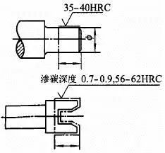
81.What are the methods for labeling surface roughness? Norm 9.
Answer: When parts need to be partially heat treated or plated (coated), the range should be drawn with thick dotted lines and the corresponding dimensions should be marked. The requirements can also be written in the surface roughness symbol. As shown in Figure 18.
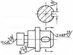
82.What are the methods for labeling surface roughness? Norm 10.
Answer: The surface roughness codes of the working surface of the center hole, the keyway working surface, chamfers and fillets can be simplified as shown below. As shown in Figure 19.
83.What are the methods for labeling surface roughness? Specification 11.
Answer: When there is no drawn tooth (tooth) shape on the working surface of gears, involute splines, threads, etc., the surface roughness code can be marked as shown below. As shown in Figure 20.
84. When other marking codes for surface roughness are ![]() , what is its meaning?
, what is its meaning?
Answer: The sampling length should be marked below the horizontal line on the long side of the symbol, indicating the sampling length I= 2.5mm.
85. When other marking codes for surface roughness are  , what is its meaning?
Answer: When the roughness requirements are obtained by a specified processing method, text can be marked on the horizontal line on the long side of the symbol.
86. When other marking codes for surface roughness are ![]() , what is its meaning?
, what is its meaning?
Answer: When you need to control the texture direction of surface processing, you can add the texture direction symbol to the right of the symbol.
87. When other marking codes for surface roughness are  , what is its meaning?
Answer: The machining allowance should be marked on the left side of the symbol, indicating that the machining allowance is 2mm.
88. When other marking codes for surface roughness are  , what is its meaning?
Answer: It indicates the surface roughness value before plating (coating).
89. When other marking codes for surface roughness are ![]() , what is its meaning?
, what is its meaning?
Answer: It indicates the surface roughness value after plating (coating) or other surface treatment.
90.What various functions does the choice of surface roughness affect?
Answer: Surface roughness affects various functions: such as friction coefficient, wear, fatigue strength, impact strength, corrosion resistance, contact stiffness and vibration resistance, clearance in clearance fits, bonding strength in interference fits, measurement Accuracy, thermal conductivity, electrical conductivity and contact resistance, sealing, bonding strength, painting performance, coating quality, fluid flow resistance, light reflection performance, food hygiene, appearance, spray metal quality, lubrication during steel plate stamping wait.
91. What effect does the choice of surface roughness have on the matching properties?
Answer: Affects the reliability and stability of matching performance. For clearance fits, due to initial wear, the peaks will quickly wear away, making the gap larger; for interference fits, the peaks will be flattened during assembly and pressing, reducing the actual effective interference, especially for small-size fits. To be significant. Therefore, the Ra value of a joint surface that requires high stability of fit properties, a surface with a small dynamic fit clearance, a static fit that requires a firm and reliable connection, and a large load bearing capacity should be lower, and the small size of the same tolerance level is better than the large size (especially 1 ~Level 3 tolerance level), the shaft with the same tolerance level is smaller than the value of the hole, and the matching properties are the same. The smaller the size of the part, the smaller its Ra value.
92. What effect does the choice of surface roughness have on wear resistance?
Answer: Due to the presence of peaks and valleys on the surface of the processed parts, the contact surface only has some peak contact, thereby reducing the contact area, increasing the specific pressure, and intensifying wear. Therefore, the friction surface moves faster than the non-friction surface, the rolling friction surface moves faster than the sliding friction surface, and the Ra value of the friction surface with high unit pressure is smaller.
93. What effect does the choice of surface roughness have on contact stiffness?
Answer: When two surfaces are in contact, since the actual contact area is part of the ideal contact area, the compressive stress per unit area increases, and contact deformation is likely to occur when external force is applied. Therefore, reducing the Ra value can improve the contact stiffness of the joint.
94. What effect does the choice of surface roughness have on fatigue strength?
Answer: The rougher the surface of the part, the more sensitive it will be to stress concentration, which will lead to fatigue damage of the part. Therefore, the Ra value of the surface subject to cyclic loads and parts that are prone to stress concentration, such as fillets and grooves, should be lower. The impact of surface roughness on the fatigue strength of parts varies with the material. The impact on cast iron parts is not obvious. For steel parts, the higher the strength, the greater the impact.
95. What effect does the choice of surface roughness have on impact strength?
Answer: The impact strength of the steel surface increases as the surface roughness Ra value decreases, especially at low temperatures.
96. What impact does the choice of surface roughness have on measurement accuracy?
Answer: Due to the microscopic unevenness on the surface of the workpiece, the measuring rod actually contacts the peak during measurement. Although the measuring force is not large, the contact area is small, and the force per unit area is not small, thus causing a certain amount of contact deformation. Since the microscopic unevenness of the surface has certain peaks and valleys, for example, when measuring, the measuring head and the measured surface need to slide relative to each other. This causes the measuring rod to fluctuate up and down with the peaks and valleys of the measured surface, which affects the indication value. fluctuation.
97. What impact does the choice of surface roughness have on sealing?
Answer: For static sealing surfaces without relative sliding, the bottom of the microscopic unevenness is too deep, and the preloaded sealing material cannot be completely filled, leaving gaps, causing leakage. The rougher the surface, the greater the leakage. For relatively sliding dynamic seal surfaces, due to relative motion, the microscopic roughness is generally 4~5 μm, which is more beneficial for storing lubricating oil. If the surface is too smooth, it will not only be unfavorable for storing lubricating oil, but will cause friction and wear. In addition, the quality of sealing is also related to the direction of the processing texture.
98.What effect does the choice of surface roughness have on corrosion resistance?
Answer: If the surface is rough, corrosive gas or liquid on the surface of the part will easily accumulate and penetrate into the surface layer of the part, aggravating corrosion. Therefore, the Ra value of the surface of parts working under conditions of corrosive gas or liquid should be smaller.
99. What impact does the choice of surface roughness have on the quality of metal surface coating?
Answer: After the workpiece is plated with zinc, chromium or copper, the depth of the microscopic unevenness on the surface will be doubled compared to before plating, while after nickel plating, it will be reduced by half. And because the rough surface can absorb the tensile stress generated when the sprayed metal layer is cooled, it is not easy to produce cracks. The surface must have a certain roughness before spraying the metal.
100. What effect does the choice of surface roughness have on vibration and noise?
Answer: The surface of the moving pairs of mechanical equipment is rough and uneven, which will produce vibration and noise during operation. This phenomenon is more obvious for high-speed running rolling bearings, gears, engine crankshafts, camshafts and other parts. Therefore, the smaller the surface roughness Ra value of the moving pair, the smoother and quieter the moving parts will be.


