E-Mail:sales@whalescnc.com
E-Mail:sales@whalescnc.com
The automatic tool changer is an essential component of machining centers, and its shape and structure are continuously evolving. Currently, automatic tool changers are mainly used in machining centers and turning centers. However, the automatic wheel changer for CNC grinders and the automatic mold changer for electrical machining tools are also increasing.
Ⅰ.CNC Lathe Tool Holder
The tool holder is a crucial component of the CNC lathe. It is used to install various cutting tools, and its structure directly affects the cutting performance and working efficiency of the machine tool. The commonly used ones are the rotary tool holder, the row tool holder, and the automatic tool changer with a tool magazine.
1.Rotary Tool Holder
The rotary tool holder, also known as the turret tool holder, is the most commonly used and simplest automatic tool changer on CNC lathes. The rotary tool holder uses a rotating head to install or clamp various tools for different purposes. The automatic tool changing action of the lathe is realized by the indexed rotation of the rotating head. The rotary tool holder can be designed in various forms such as a square tool holder, a hexagonal tool holder, or a disc-type axial tool holder. It can hold 4, 6, or more tools and can change tools according to the instructions of the CNC device. Figure 5-35 shows the commonly used rotary tool holder.
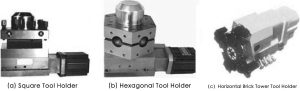
(1) Square Tool Holder and Its Working Principle
The structure of the commonly used spiral lifting vertical square tool holder on CNC lathes is shown in Figure 5-36.
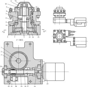
1—Axis; 2—Worm gear; 3—Tool seat; 4—Seal ring; 5—Lower tooth disc; 6—Upper tooth disc; 7—Pressure cover; 8—Tool holder; 9—Sleeve; 10—Shaft sleeve; 11—Gasket; 12—Nut; 13—Pin; 14—Base plate; 15—Bearing; 16—Coupling; 17—Shaft; 18—Sleeve; 19—Worm; 20—Switch; 21—Sleeve; 22—Compression spring; 23—Motor; 24—Pressure cover; 25—Switch
The square tool holder shown in the figure has the following tool changing process:
① Tool Holder Lifting. When the CNC device issues a tool change command, motor 23 rotates forward. Through the coupling 16 and shaft 17, the worm 19, worm gear 2, shaft 1, and shaft sleeve 10 are driven to rotate by the sliding key (or spline). There are two protrusions on the outer circle of the shaft sleeve 10, which can slide in the spiral groove of the inner hole of the sleeve 9, thereby lifting the tool holder 8 and the upper tooth disc 6 connected to the sleeve 9, separating the upper tooth disc 6 from the lower tooth disc 5, and completing the tool holder lifting action.
② Tool Holder Positioning. After the tool holder is lifted, the shaft sleeve 10 continues to rotate, simultaneously rotating the tool holder 8 by 90° (if not in place, the tool holder can continue to rotate 180°, 270°, 360°), and the micro switch 20 sends a signal to the CNC device.
③ Tool Holder Clamping. After the tool holder is positioned, the control signal sent by the micro switch causes the motor 23 to reverse. The pin 13 positions the tool holder 8 so that it does not rotate back with the shaft sleeve 10. As a result, the tool holder 8 moves downward, and the upper and lower tooth discs are clamped together. The continuous rotation of the worm 19 produces axial displacement, compressing the spring 22, and the outer curved surface of the sleeve 21 activates the switch 20. The motor 23 stops rotating, completing a positioning.
(2) Hexagonal Tool Holder
The hexagonal tool holder of the CNC lathe is suitable for the machining of disc parts. When machining shaft parts, it can be replaced with a square tool holder. The installation dimensions at their bottoms are the same, making them very convenient to interchange. Therefore, they are widely used in CNC lathes.
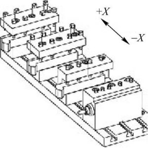
2. Row Tool Holder
The row tool holder is generally used for small CNC lathes to process bar materials. Its structure consists of tool clamps holding various tools for different purposes, arranged along the X-axis direction of the machine tool on the transverse slide. The typical arrangement of tools is shown in Figure 5-37. This type of tool holder is convenient in terms of tool layout and machine tool adjustment. Depending on the specific turning process requirements of the workpiece, various tools for different purposes can be combined at will. After the first tool completes the turning task, the transverse slide only needs to move along the X-axis by a predetermined distance as per the program, and the second tool will reach the machining position, thus completing the machine tool’s tool change action.
3. automatic Tool Changer with magazine
With the further development of CNC lathes towards flexibility, sometimes it is necessary to process a wide range of workpieces in small and medium batches. Sometimes, based on the process requirements of the workpiece, a large number of tools are needed. In this case, an automatic tool changer with a tool magazine should be used. The automatic tool changer with a tool magazine consists of a tool magazine and a tool exchange mechanism.
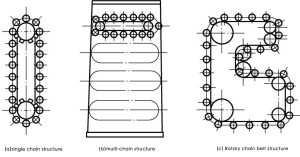
(1) Chain Rotary Tool Magazine
Chain rotary tool magazines can generally be divided into three different forms based on their structure: single-chain structure, multi-chain structure, and rotary chain belt structure, as shown in Figure 5-38.
The chain rotary tool magazine mainly consists of three parts: the tool spindle drive mechanism, the tool indexing mechanism, and the tool change clamping mechanism. The entire tool magazine is installed on the tool holder slide, and the tool magazine moves along the X-axis with the tool holder slide. This tool magazine structure is compact, can automatically change tools along the shortest path, the number of power tools can be expanded as needed, the manufacturing cost is relatively low, and it is suitable for medium and small turning centers.
Figure 5-39 shows a CNC lathe equipped with a chain tool magazine, where tools are exchanged through a robotic arm.
(2) Disc Rotary Tool Magazine
The disc rotary tool magazine is shown in Figure 5-40. In the disc rotary tool magazine, tools can be placed along the axial, radial, or oblique direction of the tool magazine’s main spindle.

Ⅱ.Automatic Tool Changer in Machining Centers
In machining centers, the device used to transfer and load/unload tools between the tool magazine and the spindle is called the tool exchange device. Its function is to replace the tools pre-stored in the tool magazine onto the spindle in sequence according to the requirements of the process.
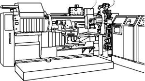
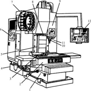
The automatic tool changer on the machining center consists of a tool magazine and a tool exchange device, used to exchange tools or tools between the spindle and the tool magazine. Figure 5-41 shows the JCS-018A vertical boring and milling machining center produced by the original Ministry of Mechanical Industry’s Beijing Machine Tool Research Institute. The automatic tool changer of this machine tool consists of components such as the tool magazine 7 and the robot arm 8. When a tool change is needed, the CNC system issues a command, and the robot arm (or through other means) takes the tool from the tool magazine and loads it into the spindle hole.
1. Requirements for Automatic Tool Changers in Machining Centers
① Appropriate tool magazine capacity.
② Short tool change time.
③ Small tool change space.
④ Reliable and stable operation.
⑤ High tool repeat positioning accuracy.
⑥ Accurate tool identification.
2. Tool Magazine
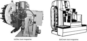
There are mainly two types of tool magazines used in machining centers: the disc-type tool magazine and the chain-type tool magazine, as shown in Figure 5-42. The disc-type tool magazine has a relatively small tool holding capacity, suitable for small machining centers. The chain-type tool magazine has a large tool holding capacity, suitable for medium and large machining centers.
3. Tool Change Methods
There are generally two tool change methods for machining centers:
(1) Tool Change Using a Robot Arm in Conjunction with the Tool Magazine
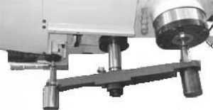
The tool is selected from the tool magazine, and then the robot arm completes the tool change action. This is the tool change method commonly adopted by machining centers. Depending on the machine tool structure, the form and action of the robot arm vary, including single-arm, double-arm, rotary, rail-type, etc. Figure 5-43 shows a single-arm double-claw robot arm, which is one of the most commonly used types in machining centers.
(2) Direct Tool Change Between the Tool and the Spindle (Without a Robot Arm)
The relative movement between the tool magazine and the machine tool spindle is used to achieve the tool exchange action, completing the tool change. This method is suitable when the tool storage position in the tool magazine aligns with the spindle tool direction.
4. Automatic Tool Change Process
Taking the JCS-018A vertical boring and milling machining center’s automatic tool change process as an example, the automatic tool change process is illustrated. The schematic diagram is shown in Figure 5-44. After the previous process is completed, the spindle is in the “ready to stop” position, and the tool is changed by the automatic tool changer. The process is as follows:
① The tool sleeve rotates 90° downward. The machine tool’s tool magazine is located on the left side of the column. The tool’s installation direction in the tool magazine is perpendicular to the spindle, as shown in Figure 5-44. Before the tool change, the tool magazine 2 rotates to bring the tool 5 to be changed to the tool change position. Then, the tool sleeve 4 with the tool 5 is flipped downward by 90°, aligning the tool axis parallel to the spindle axis (as shown by the dashed line in the figure).
1—Robot arm; 2—Tool magazine; 3—Spindle; 4—Tool sleeve; 5—Tool
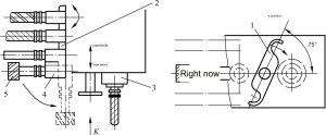
② The mechanical arm rotates 75°. As shown in Figure 5-44 from the K perspective, when the machine tool is cutting, the centerline of the arm of the mechanical arm forms a 75° angle with the line connecting the spindle center to the tool center at the tool change position. This position is the original position of the mechanical arm. The first action of the mechanical arm during tool changing is to rotate clockwise by 75°, with both claws grabbing the tool handles on tool magazine 2 and spindle 3 respectively.
③ Tool loosening. After the mechanical arm grabs the tool handle on the spindle, the automatic clamping mechanism of the tool loosens the tool.
④ The mechanical arm pulls out the tool. The mechanical arm descends, pulling out two tools simultaneously.
⑤ Exchange the positions of the two tools. The mechanical arm, holding two tools, rotates counterclockwise by 180° (viewed from the K direction), exchanging the positions of the spindle tool and the tool in the tool magazine.
⑥ The mechanical arm inserts the tool. The mechanical arm rises, inserting the tools into the spindle taper hole and the tool holder respectively.
⑦ Tool clamping. After the tool is inserted into the spindle taper hole, the automatic clamping mechanism clamps the tool.
⑧ Hydraulic cylinder reset. The hydraulic cylinder that drives the mechanical arm to rotate counterclockwise by 180° resets, and the mechanical arm remains stationary.
⑨ The mechanical arm reverses 75°. The mechanical arm reverses by 75°, returning to its original position.
⑩ The tool holder rotates upward by 90°. The tool holder, with the tool, flips upward by 90°, preparing for the next tool selection.
5.Structure of the Robotic Arm
The tool-changing robotic arm used on the vertical boring and milling machining center is a rotary single-arm dual-claw robotic arm. During the automatic tool-changing process, the robotic arm completes actions such as grabbing the tool, pulling out the tool, exchanging the positions of the tools on the spindle and the tool magazine, inserting the tool, and resetting.
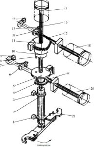
As shown in Figure 5-45, the schematic diagram of the transmission structure of the JCS-018A robotic arm. As described when introducing the tool magazine structure, after the tool sleeve rotates downward by 90°, it presses the position switch and sends a signal for the robotic arm to grab the tool. At this time, the robotic arm 21 is in the position shown in Figure 5-45. The right chamber of the hydraulic cylinder 18 is pressurized, and the piston rod pushes the rack 17 to move to the left, causing the gear 11 to rotate. When the gear rotates, it drives the robotic arm shaft to rotate, making the robotic arm rotate 75° to grab the tool. When the tool grabbing action is completed, the stop ring 12 on the rack 17 presses the position switch 14, sending a signal to pull out the tool. Then, the upper chamber of the hydraulic cylinder 15 is pressurized, and the piston rod pushes the robotic arm shaft 16 to descend and pull out the tool. As the arm shaft 16 descends, the transmission plate 10 also descends, and its lower end pin 8 inserts into the pin hole of the connecting plate 5. The connecting plate 5 and the gear 4 below it are also connected by screws, and they are loosely fitted on the shaft 16. After the tool-pulling action is completed, the stop ring 2 on the arm shaft 16 presses the position switch 1, sending a tool exchange signal. At this time, the right chamber of the hydraulic cylinder 20 is pressurized, and the piston rod pushes the rack 19 to move to the left, causing the gear 4 and the connecting plate 5 to rotate. Through the pin 8, the transmission plate drives the robotic arm to rotate 180°, exchanging the positions of the tools on the spindle and the tool magazine. After the tool exchange action is completed, the stop ring 6 on the rack 19 presses the position switch 9, sending a tool insertion signal. The lower chamber of the hydraulic cylinder 15 is pressurized, and the piston rod raises the robotic arm shaft to insert the tool, while the pin 8 below the transmission plate moves out of the pin hole of the connecting plate 5. After the tool insertion action is completed, the stop ring on the shaft 16 presses the position switch 3, causing the left chamber of the hydraulic cylinder 20 to be pressurized, and the piston rod pushes the rack 19 to move to the right to reset, while the gear 4 idles, and the robotic arm remains stationary. After the rack 19 is reset, the stop ring on it presses the position switch 7, causing the left chamber of the hydraulic cylinder 18 to be pressurized, and the piston rod pushes the rack 17 to move to the right. Through the gear 11, the robotic arm reverses 75° to reset. After the robotic arm is reset, the stop ring on the rack 17 presses the position switch 13, sending a tool change completion signal, causing the tool sleeve to flip upward by 90°, preparing for the next tool selection. Meanwhile, the machine tool continues the subsequent operations.
1, 3, 7, 9, 13, 14 – Position switches; 2, 6, 12 – Stop rings; 4 – Gear; 5 – Connecting plate; 8 – Pin; 10 – Transmission plate; 11 – Gear; 15, 18, 20 – Hydraulic cylinders; 16 – Arm shaft; 17, 19 – Racks; 21 – Robotic arm.
6.Fault Diagnosis of Tool Post, Tool Magazine, and Tool Changing Device
The fault diagnosis of the tool post, tool magazine, and tool changing device is shown in Fault Diagnosis Table. The turret tool post of the CNC lathe also has some common faults, which are also listed in Fault Diagnosis Table.
Fault Diagnosis Table
| No. | Fault phenomenon | cause of issue | Method of exclusion |
| 1 | The turret frame does not pick up the action | Whether the control system has a work command output signal | If it fails to output, please ask electrical personnel to troubleshoot it. |
| Lift the solenoid and disconnect or lift the valve stem and get stuck. | Repair or remove dirt, replace solenoid valve | ||
| Not enough repulsion | Check the fuel tank and readjust the pressure | ||
| Pick up if the hydraulic cylinder is worn or the sealing ring is damaged | Repair the damaged part or replace the sealing ring | ||
| The mechanical part connected to the turret lift is worn out | Repair damaged parts or replace parts | ||
| 2 | Turret indexes slowly or does not index | Check whether there is an index signal output | Check whether the indexing relay is closed |
| The index solenoid valve is disconnected or the valve stem is stuck. | Repair or replace | ||
| Not enough pressure | Check whether there is any hydraulic failure and adjust to the rated pressure | ||
| Index speed throttle valve stuck | Clean the throttle valve or replace it | ||
| Hydraulic pump damaged and stuck | Repair or replace hydraulic pump | ||
| Camshaft gland is too tight | Adjust the adjusting screw | ||
| Lifting the hydraulic cylinder causes friction and wear on the turret plane | Loosen the continuous pressing plate to perform an indexing test, remove the adjustment pad under the connecting plate and the ground bearing, and keep the relative gap at 0.04mm. | ||
| Installation accessories are not matching | Re-adjust attachment installation to reduce indexing impact | ||
| 3 | Teeth bumping during turret indexing | The lifting delay time is short | Adjust the pick-up delay parameters and increase the delay time |
| 4 | The turret is not in place | The impact block and position selection switch on the index plate are loose, causing the transmission signal to expire or lag when the turret is in place. | Remove the protective cover, put the turret outside in the upright position, readjust the positions of the impact block and the position selection switch and tighten them. |
| The spline gap between the upper and lower connecting disks and the central shaft is too large, resulting in a large displacement deviation. It is easy to hit the top of the tooth when falling, causing it to not reach the position. | Re-adjust the position of the vertical connecting plate and the central axis. If the gap is too large, replace the parts. | ||
| The gap between the indexing cam and the indexing plate is large | Use a feeler gauge to test the roller and cam, adjust the cam to the middle position, and keep the left and right movement of the turret between the two teeth to ensure smooth engagement when it is dropped; swing the turret by hand when picking it up, and the momentum does not exceed 1/3 of the two teeth. | ||
| The cam moves on the shaft | Adjust and tighten the nut securing the index cam | ||
| The axial preload of the indexing cam is too large or there is mechanical interference, causing the turret to not be in place. | Readjust the preload force to eliminate interference | ||
| 5 | The turret rotates continuously | The two counting switches do not count at the same time or the reset switch is damaged. | Adjust the positions of the two impact blocks and the counting delays of the two counting switches, and repair the reset switch. |
| The 24V power supply on the turret is broken. | Connect the power cord | ||
| 6 | Poor repeatability of turret knife | Insufficient hydraulic clamping force | Check pressure and adjust to rated value |
| The upper and lower chainrings were impacted and their positioning became loose. | Reset fixed | ||
| There is dirt on both teeth or the roller needle has fallen off in the middle of the teeth. | Remove dirt, keep the turret clean, and repair and replace needle rollers | ||
| There is mechanical interference (such as iron filings) when the turret is dropped and clamped. | Check to eliminate mechanical interference | ||
| The clamping hydraulic cylinder is roughened or worn | Repair the roughened and worn parts and replace the sealing ring | ||
| Turret hydraulic cylinder is roughened or worn | Repair and adjust the pressure plate and wedge iron, the 0.04mm feeler gauge plug is not in place | ||
| 7 | Tool cannot be clamped | Insufficient air pressure in the air pump | Keep the air pump pressure within the rated range |
| Pressure leakage | Turn off boost | ||
| The cutting tool clamping hydraulic cylinder is leaking | Replace the sealing device to ensure that the hydraulic cylinder does not leak. | ||
| The nut on the tool release spring is loose | Tighten the nut | ||
| 8 | The tool cannot be loosened after being clamped | The spring pressure of the lock knife is too tight | Adjust the screw on the lock knife spring so that the maximum load does not exceed the rated value |
| 9 | The tool holder cannot clamp the tool | Check the adjusting nut on the knife sleeve | Rotate the adjusting nuts at both ends of the tool holder clockwise to tighten the spring and tighten the clamping pin. |
| 10 | Robot tool changing speed is too fast | The air pressure is too high or the throttle valve opening is too large | Ensure the pressure and flow of the air pump, and rotate the throttle valve until the tool changing speed is appropriate. |
| 11 | Can’t find the knife when changing the knife | The combined travel switch, proximity switch and other components used for tool position coding are damaged, have poor contact or have reduced sensitivity. | Replace damaged components |
| 12 | The tool holder in the tool magazine cannot clamp the tool | Check the adjusting nut on the knife holder | Turn the adjusting nuts on both sides of the tool holder clockwise to tighten the spring and the clamping pin. |
| 13 | The tool magazine cannot rotate | The coupling connecting the motor shaft and the worm shaft is loose | Tighten the screws on the coupling |
| 14 | The tool falls off the robot | Check tool weight | The weight of the tool must not exceed the specified value |
| The manipulator clamping pin is damaged or does not pop out | Replace clamping pin or spring | ||
| 15 | Knife dropped during tool exchange | The spindle box does not return to the tool change point or the tool change point drifts when changing tools. | Re-operate the spindle box movement to return it to the tool change point and reset the tool change point. |
| When the robot grasps the knife, it is not in place and starts to pull out the knife. | Adjust the manipulator arm so that the arm claws grasp the knife handle before pulling out the knife |


